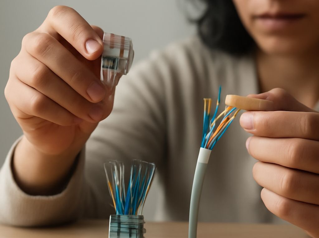
Network Cable Types and T568A RJ45 Wiring
The best network cable type depends on the medium, required distance, data rate, installation environment, and connector. Copper twisted-pair cable is the usual choice for Ethernet to desktops, access points, switches, and cameras. Fiber is better for long runs, high bandwidth, and electrical isolation, while coax remains useful for cable modem, television, radio, and some MoCA networks.
For a typical copper Ethernet link, Cat5e or better solid cable, terminated with compatible 8P8C plugs commonly called RJ45 connectors, supports up to 100 meters when installed correctly. The T568A RJ45 wiring standard places all eight conductors in a defined order. Both ends must use T568A for a straight-through cable.
Network cable types: choose copper, fiber, or coax by application
- Twisted-pair copper: Cat5e, Cat6, and Cat6A Ethernet cable is the practical choice for most local-area networks. It uses four balanced twisted pairs and normally terminates in 8P8C modular plugs or keystone jacks. Copper supports Power over Ethernet and is simple to install, test, and replace.
- Fiber optic: Fiber carries data as light through glass or plastic rather than electrical signals. Multimode fiber, such as OM3 or OM4, suits shorter building or data-center links. Single-mode fiber, such as OS2, is used for longer campus, carrier, and backbone runs. Common connectors include LC and SC, and the network equipment requires compatible optical transceivers.
- Coaxial cable: Coax has a central conductor, dielectric insulation, metallic shield, and outer jacket. RG-6 with an F connector is common for cable broadband, television, and MoCA. BNC and N connectors support other radio, video, and networking applications. Coax is not interchangeable with twisted-pair Ethernet and does not use an RJ45 pinout.
Copper Ethernet normally has a maximum 100-meter channel: up to 90 meters of permanent cable plus up to 10 meters of patch cords. Fiber distances vary substantially by fiber type, transceiver, and data rate. Coaxial distance also depends on cable specification, signal frequency, amplifiers, and the connected equipment.
Compare category, shielding, conductors, jackets, connectors, distance, and uses
Category identifies the performance capability of copper twisted-pair cable. The category should meet or exceed the network equipment and required distance.
- Cat5e: Rated to 100 MHz and commonly used for 10BASE-T, 100BASE-TX, and 1000BASE-T Gigabit Ethernet up to 100 meters. It is a sensible minimum for ordinary new Ethernet patching.
- Cat6: Rated to 250 MHz. It supports Gigabit Ethernet to 100 meters and can support 10Gbps for shorter runs, commonly up to 55 meters depending on installation and interference.
- Cat6A: Rated to 500 MHz and designed for 10Gbps to 100 meters. Its larger diameter and stricter separation requirements make it useful for new installations expected to carry higher data rates.
- Cat8: Designed for high-speed data-center links, including 25Gbps and 40Gbps over short distances, generally up to 30 meters. It is usually shielded and less practical for ordinary office cabling.
Shielding controls electromagnetic interference but can make cable thicker, less flexible, and more demanding to install. The common constructions include:
- U/UTP: Unshielded cable with unshielded pairs. It is flexible, inexpensive, and suitable for most office and residential Ethernet runs.
- F/UTP: A foil shield surrounds all four unshielded pairs.
- U/FTP: Each pair has its own foil shield, with no overall shield.
- S/FTP: A braided overall shield surrounds individually foil-shielded pairs. It provides strong interference protection but requires compatible shielded connectors and proper bonding.
Shielded cable is useful near motors, fluorescent lighting, radio transmitters, industrial equipment, or dense cable bundles. It should not be selected merely because its category number is higher. A shielded link needs shielded jacks or plugs and a correctly bonded path; otherwise, the shield benefit may be reduced.
Conductor construction also affects the application. Solid copper conductors have lower signal loss and are intended for fixed in-wall or patch-panel cable. Stranded copper is more flexible and is preferred for short patch cords. A plug must match the conductor type and wire gauge. Pure copper cable is the reliable choice; copper-clad aluminum cable can have higher resistance, poorer PoE performance, and compatibility problems.
Jacket selection must match the installation. PVC is common for ordinary exposed indoor patching. CMP or plenum cable is required where local building rules require low-smoke, fire-resistant cable in air-handling spaces. CMR or riser cable is intended for vertical pathways. Outdoor runs need a jacket rated for sunlight, moisture, temperature, or direct burial as applicable.
Use an unshielded or shielded 8P8C connector that matches the cable category, conductor type, diameter, and solid or stranded construction. A strain-relief boot can protect a patch cable, but it does not correct an incompatible plug or poor termination.
T568A RJ45 wiring pinout: plug orientation, eight colors, pair roles, and straight-through use
To read the T568A pinout, look into the front contact side of the modular plug with the gold contacts facing up and the locking latch underneath. Pin 1 is on the left and pin 8 is on the right. The cable enters from the rear of the plug.
- Pin 1: white with green stripe
- Pin 2: solid green
- Pin 3: white with orange stripe
- Pin 4: solid blue
- Pin 5: white with blue stripe
- Pin 6: solid orange
- Pin 7: white with brown stripe
- Pin 8: solid brown
In T568A, the green pair occupies pins 1 and 2, the orange pair occupies pins 3 and 6, the blue pair occupies pins 4 and 5, and the brown pair occupies pins 7 and 8. Pair conductors stay together even when the two wires are separated by another pair in the pin sequence. That separation is part of the Ethernet design and must not be rearranged.
Pins 1 and 2 form one data pair, and pins 3 and 6 form the other pair used by 10Mbps and 100Mbps Ethernet. Gigabit Ethernet uses all four pairs, so a cable can pass an older two-pair connection while still failing to support 1000BASE-T. Power over Ethernet can also use the pairs, depending on the powering method and equipment.
A straight-through T568A cable has the same sequence at both ends: T568A on one end and T568A on the other. It is used for normal connections such as a computer to a switch, an access point to a switch, or a patch panel to a switch. T568B at both ends is also straight-through, but combining T568A at one end with T568B at the other creates a crossover cable. Modern network interfaces commonly support automatic crossover detection, but consistent T568A termination remains the correct structured-cabling practice when T568A is specified.
Terminate and test: preserve pairs and verify the T568A wire map
Before termination, select cable and plugs that match. Use solid-conductor plugs for solid horizontal cable and stranded-conductor plugs for flexible patch cable. A standard modular crimp tool, cable jacket stripper, flush cutter, and wire-map tester are sufficient for a basic copper termination.
- Cut the cable cleanly. Leave enough length to route the cable without sharp bends or tension. Avoid crushing or sharply bending the cable, especially Cat6A and shielded types.
- Strip only the required jacket. Remove enough outer jacket to arrange the conductors, typically about 25 to 40 millimeters for a modular plug. Do not nick the insulation or drain wire. Keep the pairs twisted as close to the plug as the connector design allows.
- Separate and arrange the pairs. Untwist the conductors only as much as necessary. Excessive untwisting increases crosstalk and can cause a category or certification failure. Arrange the wires from left to right in the T568A order: white-green, green, white-orange, blue, white-blue, orange, white-brown, brown.
- Trim the conductors evenly. Hold the arranged wires firmly, cut their ends square, and insert them into the plug with pin 1 on the left when viewed from the contact side. Each conductor should enter its own channel and reach the front of the plug.
- Check the jacket position. The outer jacket should extend inside the plug far enough for the plug’s strain-relief tab to clamp the jacket, not just the individual conductors. This prevents movement from pulling the contacts loose.
- Crimp once, firmly. Place the plug in the correct die of the crimp tool and compress it fully. The contacts should pierce the conductor insulation, and the strain relief should grip the jacket. Do not reuse a plug after a failed crimp.
- Repeat T568A at the other end. For a straight-through cable, use the identical eight-color sequence on both ends. Keep the twists and jacket support consistent at both terminations.
Connect one end of the finished cable to the main unit of a wire-map tester and the other end to its remote unit. A correctly terminated T568A straight-through cable should report the following one-to-one map:
- 1 to 1: white-green
- 2 to 2: green
- 3 to 3: white-orange
- 4 to 4: blue
- 5 to 5: white-blue
- 6 to 6: orange
- 7 to 7: white-brown
- 8 to 8: brown
An open indicates a broken conductor, a conductor that did not reach the contacts, or a failed crimp. A short indicates contact between conductors. A reversed or crossed result means wires are in the wrong positions at one end. A split-pair result means continuity may appear correct by pin number, but conductors from different twisted pairs have been mixed; an advanced tester is needed to detect this reliably. After correcting any fault, retest both the wire map and, for a performance-certified installation, insertion loss, crosstalk, and length against the cable category.