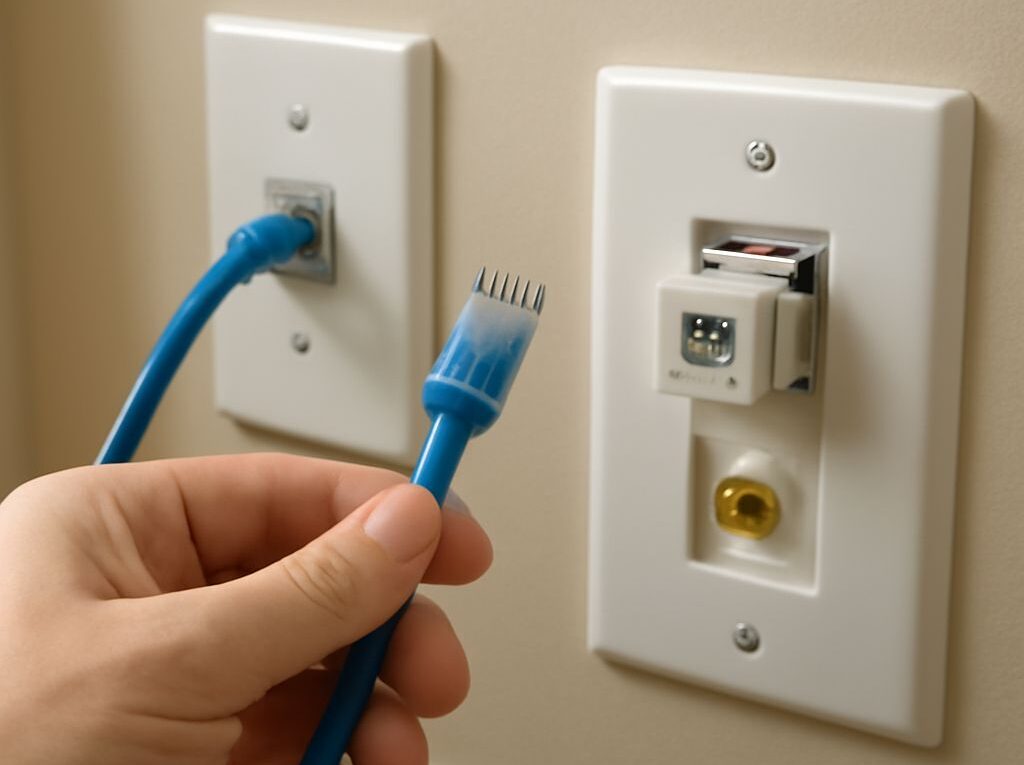
Ethernet Cabling: RJ45 Wiring for an Ethernet Wall Plate
A reliable Ethernet drop uses solid-copper Cat5e or Cat6 in-wall cable, a matching keystone RJ45 jack, and an Ethernet wall plate that accepts the jack. The cable should run from a patch-panel port to the wall plate, with a patch cord connecting the switch to the patch panel and another connecting the wall plate to the device.
Use either T568A or T568B, but keep the same standard at both ends of the permanent cable. Protect the run during installation, preserve the pair twists at each termination, then verify the finished cabling with a wire-map tester and a negotiated link-speed check.
Choose the cable, RJ45 jack, and Ethernet wall plate
Select solid-copper Cat6 or Cat5e in-wall cable, a matching keystone jack, and a compatible wall plate
Choose solid-copper, low-voltage-rated cable designed for in-wall installation. Cat6 is a practical choice for new cabling and supports 1 Gb/s Ethernet over standard channel lengths, with higher speeds possible under the appropriate distance and equipment conditions. Cat5e is also suitable for many 1 Gb/s runs. Avoid copper-clad aluminum (CCA) cable because its electrical and mechanical performance is not equivalent to solid copper.
Use a keystone RJ45 jack rated for the cable category and conductor size. Most wall plates accept one or more keystone modules, so the plate, jack, and low-voltage wall bracket should be compatible. A shielded cable requires compatible shielded jacks and patch-panel hardware, along with the correct grounding arrangement. For ordinary residential and office drops, unshielded twisted pair (UTP) is usually simpler.
Use factory-made stranded patch cords between the switch and patch panel and between the wall plate and endpoint. Solid in-wall cable is intended for fixed installation and should normally terminate on punch-down jacks or a patch panel rather than directly into an ordinary modular plug.
Plan the route from the switch or patch panel to the wall plate, including cable length, slack, labels, and one wiring standard
Map the route before pulling cable. Measure from the patch-panel location to the wall box, then allow service slack at both ends and enough length to dress the cable without tension. Keep the permanent link within 90 meters; patch cords bring the total channel limit to 100 meters under common Ethernet cabling practices.
Assign an identifier before installation, such as P-12 / Office 2. Mark the cable near the patch-panel end and wall-box end, and reserve the corresponding patch-panel port and wall-plate label. Decide whether the installation will use T568A or T568B. Either standard produces a normal straight-through link when used consistently.
Run and protect the in-wall Ethernet cabling
Maintain the cable’s bend radius, keep it separated from power wiring, and avoid crushing or tightly bundling it
Pull the cable smoothly rather than jerking it. Follow the manufacturer’s minimum bend-radius specification; when no value is available, a bend radius of at least four times the cable diameter is a common minimum for unshielded data cable. Do not kink the cable around a sharp corner, crush it with staples, or pull it so tightly that the jacket deforms.
Keep Ethernet cabling separated from mains wiring, fluorescent-ballast wiring, motors, and other sources of electrical interference. Run data cable in a separate pathway where possible. If a data cable must cross a power cable, cross at approximately 90 degrees rather than running parallel. Follow the applicable electrical and building requirements for clearances, conduit, fire stopping, and penetrations.
Do not pack the cable tightly into a small box or compress it under a cover plate. Loose, wide-radius bends preserve the cable geometry and reduce return-loss problems. Avoid excessive bundling, especially with large power bundles or tightly secured cable ties.
Preserve pair twists near the termination, use strain relief, and leave service slack at the patch panel and wall box
Keep the outer jacket intact as close to the punch-down point as the jack design permits. Untwist each pair only far enough to place the conductors into the IDC terminals. Excessive untwisting changes the electrical balance and can cause a run to pass a basic continuity test while performing poorly at higher speeds.
Secure the cable with the jack’s cable clamp, retaining cap, or other strain-relief feature. The jacket, not the individual conductors, should bear pulling and handling forces. Leave a modest service loop at the patch panel and in the wall box so the jack can be removed and reterminated without pulling on the installed route. Do not leave a tightly coiled bundle that is forced into the box.
Terminate RJ45 wiring with the same T568 standard end to end
T568A pin order, 1 through 8
At a wall jack or patch panel, use the printed T568A legend and place the conductors into the corresponding IDC slots in this order:
- White-green
- Green
- White-orange
- Blue
- White-blue
- Orange
- White-brown
- Brown
T568B pin order, 1 through 8
T568B is widely used in existing installations. Its conductor order is:
- White-orange
- Orange
- White-green
- Blue
- White-blue
- Green
- White-brown
- Brown
At the wall plate, strip only the amount of jacket specified by the jack manufacturer. Separate the four pairs, follow the chosen A or B color legend printed on the jack, and press each conductor fully into its IDC slot with a compatible punch-down tool. Keep the punch-down tool aligned with the terminal. If the tool has a cutting side, orient it according to the jack instructions so excess conductor is trimmed on the correct side. Close the jack’s strain-relief cap or cable clamp after all eight conductors are seated.
Terminate the patch-panel end with the same standard. For example, a T568B wall jack must connect to the T568B positions on the patch panel. Do not use the A legend at one end and the B legend at the other for a normal structured-cabling drop. Modern network equipment may automatically correct some crossover conditions, but mixed standards can still create faults and make the installation harder to maintain.
For an RJ45 plug, hold the plug with the gold contacts facing up and the locking latch facing down. Looking into the contact side of the plug, read pins 1 through 8 from left to right. Arrange the conductors in the selected T568A or T568B order, keep the jacket under the plug’s strain tab, push all conductors fully forward, and crimp with the correct tool. A plug intended for stranded patch-cord cable may not be suitable for solid in-wall cable, so use a plug specifically rated for the cable type when a field-terminated plug is necessary.
Test, label, and verify the finished Ethernet drop
Run a continuity and wire-map test to find opens, shorts, reversed pairs, crossed pairs, and split-pair faults
Test the cable before connecting network equipment. Place the tester’s main unit at one end and its remote at the other, then run the continuity and wire-map function. A correctly terminated eight-conductor link should show pins 1 through 8 in the expected order at both ends.
- Open: a conductor is not connected or is not fully seated in an IDC slot or plug.
- Short: two conductors are electrically connected where they should not be.
- Reversed pair or pin: conductors are connected in the wrong order within a pair or at an individual pin.
- Crossed pair: a pair is connected to the wrong pair position at the far end.
- Split pair: continuity may appear correct, but conductors from different twisted pairs have been combined, disrupting the pair balance.
A basic continuity tester can identify many opens, shorts, and pin-order errors. A tester with split-pair detection is needed for reliable pair verification. If the result fails, inspect the jack legend, recheck the pin orientation, confirm that each conductor reached the bottom of its IDC slot, and reterminate the affected end. Replace damaged plugs or patch cords rather than repeatedly reusing them.
Connect the patch cord and verify the negotiated link speed at the switch and device
After the wire map passes, connect known-good patch cords at both ends. Check the switch port and the connected device for the negotiated speed and duplex status. A 1 Gb/s link is a useful expected result when the switch, network adapter, patch cords, and cable all support it. A link light alone is not sufficient because some faults still allow a slower connection.
If equipment negotiates at 100 Mb/s instead of 1 Gb/s, check all eight conductors, both patch cords, and both terminations. Gigabit Ethernet uses all four pairs, so a split pair, poor punch-down, damaged conductor, or unsuitable plug can reduce the negotiated speed even when the cable shows continuity.
Label the patch-panel port, cable, and Ethernet wall plate, then record the test result and link speed
Apply the same identifier at the patch panel, along the cable near each end, and on the Ethernet wall plate. A useful record includes the wall-plate location, patch-panel port, cable category, selected T568 standard, test result, and negotiated link speed. For example: Office 2 — P-12 — Cat6 — T568B — wire map pass — 1 Gb/s. This label lets a future technician trace the drop without opening multiple wall plates or testing unrelated ports.