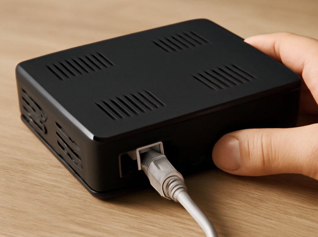
Coaxial to Ethernet: Choose Copper or Fiber by Speed
For a short, direct run, copper Ethernet is usually the simplest and least expensive choice. For an existing coaxial path, active coaxial-to-Ethernet adapters can avoid new cable installation. For long runs, high electromagnetic interference, or electrical isolation, fiber Ethernet is usually the better fit.
The relevant comparison is the complete media path: cable, connectors, adapters or transceivers, switches, endpoint count, and the way bandwidth is shared. A cable rating alone does not determine the speed or reliability that users will experience.
How coaxial to Ethernet conversion really works
Coaxial to Ethernet conversion is not a passive change from an F connector to an RJ45 connector. It requires powered electronics at the network endpoints. One adapter converts Ethernet frames into a signal designed for the coaxial cable, and another adapter converts that signal back to Ethernet.
Common systems use MoCA or another Ethernet-over-coax standard. A typical installation has the following path:
- A router or switch connects by Ethernet to a coaxial-network adapter.
- The adapter sends network traffic over the existing coaxial plant.
- A second adapter at the remote room converts the signal back to Ethernet.
- A computer, access point, switch, or other device connects to the remote adapter with an RJ45 cable.
Both adapters need power. The coaxial cable uses F-type connectors in many residential installations, while the local network side normally uses RJ45 Ethernet. The adapters, rather than the connector shapes, provide the protocol conversion, signal processing, and link negotiation.
A single point-to-point coaxial run is straightforward, but many installations use splitters to serve several rooms. In that design, multiple coaxial-to-Ethernet endpoints share the available coaxial bandwidth. A MoCA 2.5 system, for example, may advertise up to 2.5 Gbps of physical-layer capacity, but the aggregate usable throughput is divided among active nodes and reduced by protocol overhead, splitter loss, and link conditions. It is not a dedicated 2.5 Gbps connection for every room.
Existing splitters must support the adapter’s operating frequency, and amplifiers, filters, damaged cable, or disconnected coax branches can prevent the link from forming. A coax plant designed only for television may therefore need splitter replacement or branch isolation. Adapters also add processing and medium-access delay. That delay is often modest, but a direct switched Ethernet link remains the simpler path for latency-sensitive traffic.
Coax has useful advantages in buildings where it is already installed. It commonly reaches rooms that are difficult to wire with new Ethernet, provides good shielding against ordinary interference, and can support several network endpoints without opening walls. Its main limitations are shared-medium capacity, dependence on the coaxial distribution layout, powered adapters at each network endpoint, and compatibility between adapters and passive components.
Ethernet cable speed: copper limits by distance
Copper Ethernet is the practical default for most room-to-room and device-to-switch connections. The cable category, total channel length, equipment ports, and installation quality all affect the negotiated speed.
- Cat5e: commonly supports 1 Gbps to a 100-meter channel. Many modern devices can also use 2.5 Gbps over suitable Cat5e installations, and some can use 5 Gbps when conditions allow.
- Cat6: supports 1 Gbps to 100 meters and can support 10 Gbps over shorter distances, commonly up to about 55 meters depending on crosstalk and installation conditions.
- Cat6a: is designed for 10 Gbps to the full 100-meter channel and is a common choice for new 10-Gbps horizontal cabling.
The 100-meter figure includes permanent cable, patch panels, and patch cords rather than only the cable inside a wall. A switch with 1-Gbps ports cannot deliver 2.5 or 10 Gbps even when the cable is capable of it. Actual file-transfer throughput is also lower than the advertised link rate because of Ethernet, IP, and transport overhead.
Switched copper Ethernet normally gives each endpoint a dedicated full-duplex link. Devices on separate switch ports do not directly share one cable, although they compete for bandwidth on an uplink, switch fabric, or internet connection. This is different from a shared coaxial network, where several adapters may contend for the same coaxial capacity.
Copper uses familiar RJ45 connectors, is inexpensive, and can deliver power through PoE to access points, cameras, phones, and other compatible devices. That power capability is a significant advantage over fiber. The cable is, however, more vulnerable to electromagnetic interference, ground-potential differences, and poor termination. Shielded copper can help in electrically noisy areas, but the shielding must be installed and bonded correctly; an incorrectly assembled shield does not guarantee better performance.
Example: a wireless access point 20 meters from a network switch can use Cat6 with RJ45 terminations. If both switch and access point support 2.5-Gbps Ethernet, that link may negotiate above 1 Gbps; otherwise it will operate at the highest common rate, often 1 Gbps. PoE can power the access point over the same copper run.
Fiber Ethernet for reach and capacity
Fiber Ethernet is most useful when the distance exceeds copper limits, when high-speed uplinks are required, or when electrical interference and grounding make copper undesirable. Fiber is immune to electromagnetic interference and does not create a conductive path between buildings, floors, or equipment rooms.
The transceiver determines much of the usable distance and speed. Multimode fiber with modern OM3 or OM4 cabling is commonly used for high-speed building links; 10-Gbps optics may reach roughly 300 to 400 meters depending on the fiber and optic specification. Single-mode fiber supports longer distances, with appropriate optics extending 10-Gbps links from kilometers to much farther than a typical building requires. A fiber type, optic, and switch port must be selected as a compatible set.
Fiber Ethernet usually uses LC connectors in structured cabling and SFP, SFP+, or similar pluggable transceivers in switches. A device without a fiber port needs a media converter or a switch with the required optical slot at each end. These are active components and require power. Unlike copper, fiber itself cannot provide PoE to a remote endpoint, so a remote switch, converter, or access point arrangement needs local electrical power.
Most ordinary fiber links are point-to-point and do not share the medium with other endpoints. A switch may still aggregate traffic from many devices onto one fiber uplink, so the uplink speed and switch capacity remain important. Specialized passive optical networks are a different architecture with their own shared-bandwidth rules.
Fiber transceivers and converters add cost and configuration requirements, but the optical cable can provide substantial capacity and reach. Propagation through fiber is not automatically lower latency than every copper path; endpoint electronics, switching, serialization, and the number of network hops matter. Fiber is chosen primarily for distance, interference immunity, capacity, and electrical isolation rather than a cable-only latency claim.
Example: a 10-Gbps SFP+ switch port can connect through OM4 multimode fiber and compatible 10-Gbps optics to another switch in the same building. For a longer campus or building-to-building link, single-mode fiber with matching long-reach optics is more appropriate. Each end needs a compatible switch port or powered media converter.
Choose and test the complete media path
Selection starts with the endpoints and the installed route, not with a cable label. Confirm these factors before purchasing hardware:
- Distance: measure the full channel, including patch panels and service loops. Use copper within its verified category limit, coax adapters where a usable coax plant already exists, and fiber when the route exceeds copper distance or requires greater capacity.
- Required speed: check the actual ports on routers, switches, computers, and access points. A 10-Gbps cable path cannot make a 1-Gbps endpoint faster.
- Bandwidth sharing: treat a multiroom coax network as an aggregate resource. A switched copper link or point-to-point fiber link is more predictable for a dedicated connection, while its switch uplinks may still be shared.
- Interference and isolation: use fiber near heavy motors, radio equipment, high-voltage infrastructure, or between buildings. Use correctly installed copper where PoE and simple serviceability are more important.
- Connectors and active equipment: match RJ45 copper ports, coaxial adapters and splitters, or fiber connectors and optics. Include power outlets for every adapter, converter, and remote switch.
- Endpoint count: one coax adapter pair creates a simple link; additional coax adapters share the coaxial medium. A switch at the remote end can serve multiple devices without adding more long cable runs.
Three common designs illustrate the choice:
- Short copper run: connect a 20-meter access-point run with Cat6 and RJ45 connectors. Use PoE if supported, and select 1-, 2.5-, or 10-Gbps ports according to the endpoint requirements.
- Reused coax path: connect the router or main switch to a powered coaxial-to-Ethernet adapter, pass through compatible coax and splitters, and install a second adapter in the remote room. Verify that every adapter is on the same usable coax network, then connect a remote switch or device by Ethernet.
- Long fiber link: connect compatible SFP or SFP+ ports with the specified multimode or single-mode fiber and matching optics. Use a powered media converter at either end when the switches lack optical ports, and provide local power for the remote equipment.
Testing should confirm more than link lights. First check that both endpoints negotiate the intended speed and full-duplex mode. For copper, inspect the termination, run a wire-map test, and use a cable certifier when the installation must meet a category specification. For coax, check the adapter-reported physical rate, splitter compatibility, signal quality, and error counters. For fiber, verify optic compatibility, connector cleanliness, polarity, insertion, and received-light status.
Finally, test traffic in both directions with a tool such as iperf3 while monitoring packet loss, retransmissions, interface errors, and latency. A successful path should negotiate at the expected rate, sustain the required throughput under normal endpoint load, and show no rising error counters. If the negotiated rate is unexpectedly low, isolate each cable segment, adapter, optic, splitter, and switch port rather than replacing the entire path at once.