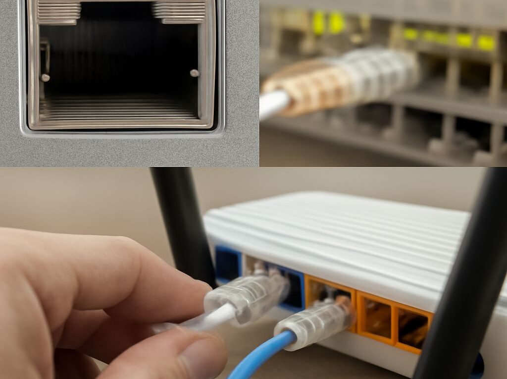
WAN Port vs LAN Port: An Enterprise Network Architecture Guide
In an enterprise network architecture, the WAN port vs LAN port distinction marks the first security and routing boundary. The WAN side faces the ISP or carrier circuit and carries traffic toward public networks; the LAN side faces internal switches, users, servers, and wireless access points. That handoff is where addressing changes, firewall policy starts, and segmentation becomes visible in day-to-day traffic flow.
Most enterprise designs follow the same path: the external circuit terminates on an edge device, that device routes or filters traffic, internal switching distributes it into VLANs or subnets, and access points or wired ports deliver it to endpoints. The details vary by vendor, but the logical sequence stays the same.
WAN Port vs LAN Port: Where the Boundary Sits
Physical ports versus network scope
A WAN port is the interface on a router or firewall that connects to the outside network. It often receives a public IP address, a provider-assigned address, or a handoff from an ONT, modem, or carrier edge device. A LAN port connects to the internal side of the enterprise, usually into a switch, a distribution block, or a directly attached device such as a server, controller, or access point.
The port label describes direction and trust, not cable type. A single appliance can have one WAN interface and several LAN interfaces, or it can present multiple LAN ports that each map to separate segments. In enterprise network architecture, the important point is the boundary: traffic entering the WAN side is untrusted by default, while traffic on the LAN side is handled according to internal policy.
- WAN side: Internet, MPLS, SD-WAN, or other carrier-facing circuits.
- LAN side: Internal VLANs, subnets, voice networks, server networks, and guest networks.
- Boundary function: Routing, NAT, filtering, logging, and often VPN termination.
How the first hop leaves the edge
Traffic from a user device does not jump directly to the internet. It first reaches an access switch or wireless access point, then moves to the LAN gateway, usually a firewall or router. From there, the default gateway forwards it across the WAN port if the destination is external.
Inbound traffic follows the reverse path and is typically constrained by policy. A public service such as a VPN portal or web application may be published through a firewall rule or reverse proxy, but most internal hosts remain hidden behind private addressing and NAT. That separation is what makes the WAN-to-LAN boundary the core control point for access, exposure, and troubleshooting.
Routers, Firewalls, and Switches in the Traffic Path
Addressing, NAT, and default gateways
The edge router or firewall connects two different addressing domains. On the WAN side, it uses provider-facing addressing and upstream routing. On the LAN side, it usually serves as the default gateway for one or more internal subnets. Endpoints send traffic to that gateway when the destination is outside their local network.
NAT is common when private addresses such as 10.0.0.0/8, 172.16.0.0/12, or 192.168.0.0/16 need to reach public destinations. NAT translates many internal addresses to one or more external addresses, reducing exposure and conserving public space. In enterprise environments, routing between internal subnets may occur without NAT, while internet-bound traffic is still translated at the edge.
- Router role: Chooses the next hop and moves packets between networks.
- Firewall role: Applies policy, stateful inspection, VPN, and segmentation controls.
- Gateway role: Provides the reachable address that hosts use to exit their subnet.
Switching, VLANs, and security boundaries
Switches carry traffic inside the LAN by learning MAC addresses and forwarding frames to the correct port or uplink. In a modern enterprise, switching is rarely flat. Instead, access switches connect endpoints into VLANs that map to user groups, device classes, or trust levels. The router or firewall then routes between those VLANs when policy allows.
This creates practical security boundaries inside the building, not just at the internet edge. A finance subnet, a server VLAN, a guest network, and a printer segment can all share the same switch fabric while remaining separated at Layer 3 or by access control lists. Wireless access points usually bridge clients into the same segmentation model, so a Wi-Fi user lands in the correct VLAN by SSID, authentication method, or policy assignment.
- Access switching: Connects endpoints and applies port security or 802.1X where required.
- Distribution or core switching: Aggregates uplinks and carries trunks between VLANs.
- Segmentation controls: VLANs, ACLs, firewall zones, and identity-based policy.
LAN Cable vs Ethernet Cable: What Each Term Means
Why LAN means scope and Ethernet means technology
The phrase lan cable vs ethernet cable is often used as if it describes two different products, but the terms are not equal. LAN describes the scope of the network: a local area network inside a site, building, campus, or enterprise segment. Ethernet describes the link technology used to move frames across that network, along with the cabling and signaling practices that support it.
In other words, a LAN cable is not a separate technical standard. In enterprise use, the cable is usually an Ethernet copper patch cable, fiber optic link, or structured cabling run that serves the local network. The same Ethernet family can operate in a LAN, a data center, an office floor, or an industrial environment. The network scope is local; the transport is Ethernet.
This matters because cabling decisions should be made by speed, distance, environment, and endpoint requirements, not by the word “LAN” alone.
What to specify for cables and links
For enterprise deployments, cable choices should align with the device port and the expected link speed. Copper Ethernet commonly uses Cat5e, Cat6, or Cat6A for short to medium runs, while fiber is used for longer distances, higher bandwidth, or electrical isolation. Wi-Fi access points, phones, cameras, and desktops may use copper Ethernet with PoE, while uplinks between closets or buildings often use fiber.
- Specify speed: 1 GbE, 2.5 GbE, 10 GbE, or higher.
- Specify distance: Patch lead, horizontal run, or inter-rack/inter-building link.
- Specify media: Copper or fiber, based on distance and interference.
- Specify connector and category: RJ45-based copper categories or fiber connector type.
- Specify power needs: PoE for phones, APs, cameras, and some edge devices.
Using the right term improves procurement and troubleshooting. If a link drops, the issue is usually not “LAN cable” in the abstract; it is a mismatched category, damaged patch cord, bad termination, unsupported speed, or an uplink that exceeds its designed distance.
A Resilient Segmented Enterprise Network Layout
User, server, guest, and wireless segments
A resilient enterprise design places different traffic classes into separate segments so that one failure or compromise does not spread through the whole environment. User devices normally sit in one VLAN, servers in another, guests in a restricted internet-only segment, and wireless clients in policies that mirror their role. A printer, voice phone, and contractor laptop should not all share the same trust level just because they connect to the same building.
That layout keeps routing and firewall rules readable. For example, users may reach approved internal applications, servers may accept only specific management or application ports, and guest devices may exit only through the WAN with no access to private subnets. Wireless access points participate in the same design by mapping SSIDs to VLANs or identity policies, so the cable path and the radio path obey the same controls.
- User segment: General workstation traffic with controlled access to internal services.
- Server segment: Application, database, and infrastructure hosts with tighter rules.
- Guest segment: Internet-only access with isolation from internal resources.
- Wireless segment: Policy-driven access tied to SSID, authentication, or device posture.
Redundancy and failover at the edge
Resilience starts at the WAN edge. Many enterprises use dual ISP links, dual WAN ports, or separate carriers to reduce outage risk. The firewall pair may run in high availability mode, with one unit ready to take over if the active unit fails. Internal switches may be stacked, meshed with redundant uplinks, or connected by aggregated links so a single cable or port failure does not cut off a floor or department.
Failover only helps if the design is intentional. Static routes, dynamic routing, health checks, and session synchronization all need to align so traffic can move cleanly from the primary path to the backup path. Power redundancy matters as well: dual power supplies, separate UPS feeds, and distinct circuits keep the edge alive when one source fails.
- Edge redundancy: Dual WAN circuits, dual firewalls, or active/standby pairs.
- Switch resilience: Stacking, MLAG, or redundant uplinks to the distribution layer.
- Link resilience: LACP or other aggregation where the platform supports it.
- Power resilience: UPS, dual PSUs, and separate electrical paths.
Management plane isolation and monitoring
The management plane should not share the same open path as user traffic. Switches, firewalls, APs, and controllers are easier to secure and support when they use a dedicated management VLAN, a separate out-of-band network, or a restricted admin subnet. That keeps administrative access away from general browsing, guest clients, and everyday endpoint traffic.
Monitoring should also live in a controlled management path. Logs, alerts, and telemetry from the edge and switching layers help confirm that the WAN-to-LAN handoff is working, that segmentation is enforced, and that failover actually occurs when a circuit fails. Useful signals include interface status, route changes, VPN health, DHCP scope usage, wireless controller alerts, and switch port errors.
- Isolate admin access: Limit management to known hosts and authenticated users.
- Track traffic health: Interface counters, drops, latency, and link flaps.
- Verify policy: Check VLAN membership, firewall rules, and routing tables.
- Confirm failover: Test the backup WAN, standby firewall, and alternate uplinks.