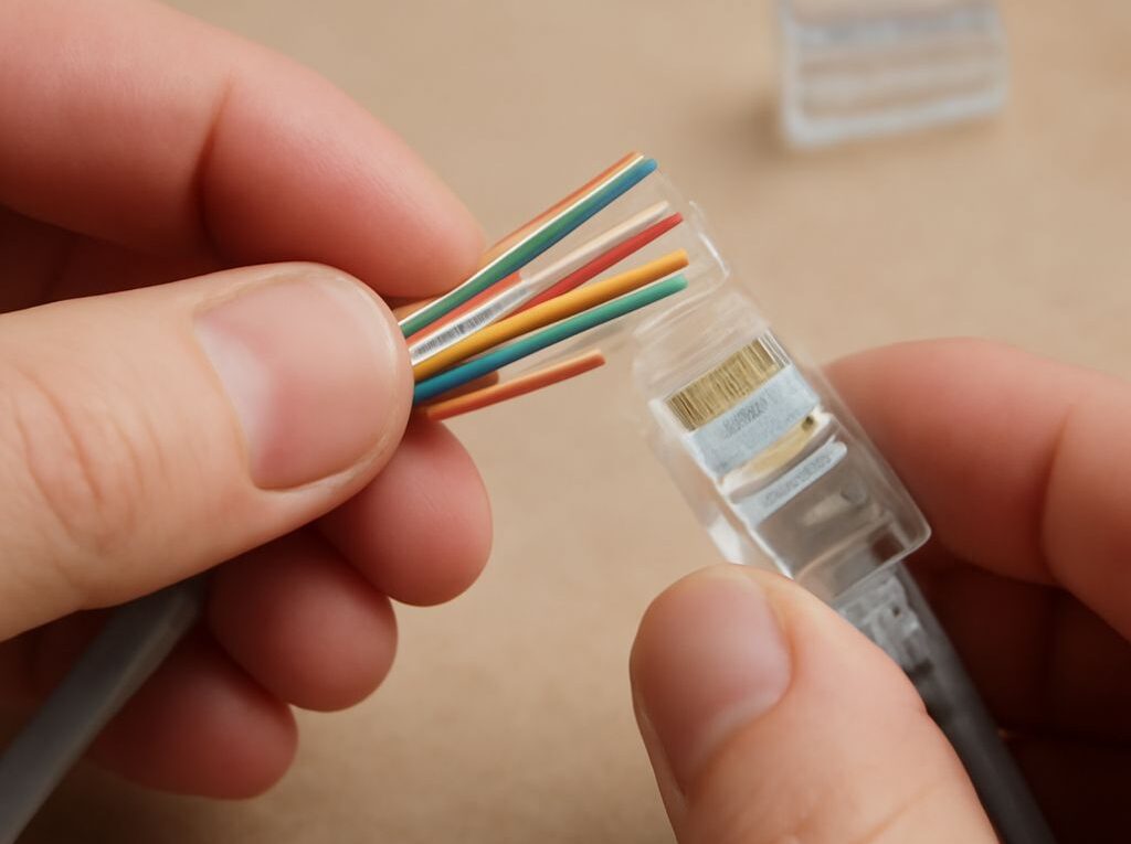
Ethernet Cable Length Limit: 100 m Channel, Cable Sizes, and Exceptions
The standard ethernet cable length limit is 100 m (328 ft) for a complete copper channel in most conventional twisted-pair Ethernet applications. That figure includes the installed link, patch-panel connections, and equipment patch cords; it does not mean that every individual Ethernet cable can be 100 m long.
The qualified distance depends on the Ethernet speed, cable category, conductor construction, temperature, connector quality, and PoE load. A typical design uses up to 90 m of permanent cable plus up to 10 m of combined patch cords. Longer paths require a switch, an active extender, or fiber rather than simply adding more passive copper cable.
Ethernet cable length limit: 100 m channel rules by speed
For the most common copper Ethernet standards, the 100 m figure is a channel limit measured from one active device to the other. It includes both the permanent link and the connecting cords.
- 10BASE-T: Up to 100 m with suitable Category 3 or better balanced twisted-pair cable. This legacy speed is rarely used in new installations.
- 100BASE-TX: Up to 100 m with Category 5 or better cable under the applicable channel requirements.
- 1000BASE-T: Up to 100 m with Category 5e or better cable. This is the usual Gigabit Ethernet distance assumption.
- 2.5GBASE-T and 5GBASE-T: Generally up to 100 m over a compliant Category 5e or better channel, provided installation, bundling, and noise conditions meet the relevant requirements.
- 10GBASE-T: Up to 100 m with Category 6A. Category 6 can support 10 Gb/s over shorter qualified distances, commonly up to about 55 m depending on alien crosstalk, bundle size, and the installation.
- 25GBASE-T and 40GBASE-T: Category 8 systems are designed for a channel of up to 30 m, not the 100 m used by lower-speed copper Ethernet.
These distances apply to balanced copper twisted pair, not to every Ethernet medium. Fiber Ethernet has different limits based on fiber type, transceiver wavelength, optical budget, and data rate. Single-pair Ethernet used in industrial or automotive applications also follows different specifications. Consequently, the ethernet length limit must be matched to the physical layer being installed.
A link that negotiates at a lower speed is not automatically a successful long-distance design. Excessive insertion loss, crosstalk, poor terminations, electromagnetic interference, or high resistance can cause errors even when a tester reports a physical length below 100 m.
Permanent link and patch-cord allocation: 90 m plus 10 m
The familiar 90 m plus 10 m rule separates the fixed installation from the flexible cords. The permanent link runs through the building infrastructure, usually from a patch panel to a telecommunications outlet or another fixed termination. It is normally limited to 90 m.
The channel adds the equipment cords and work-area cords at both ends. Their combined length is normally limited to 10 m, producing a maximum channel length of 100 m. For example, a 90 m horizontal run with a 5 m cord at each end uses the full nominal allocation.
The allocation is not permission to install 100 m of horizontal cable and then add patch cords. A 100 m permanent run would leave no allowance for equipment cords and would exceed the standard channel model once those cords were connected.
Patch cords also have different electrical characteristics from horizontal cable. Permanent cable is usually solid-conductor cable designed for fixed installation, while patch cords normally use more flexible stranded conductors. A small-gauge or unusually long patch cord can have greater resistance and attenuation than the channel model assumes.
When a design uses many cords, slim cords, or cords longer than the normal allocation, the channel should be checked using the applicable manufacturer and cabling-standard model. The total physical length may be below 100 m while the electrical performance still fails. Patch cords should use connectors rated for the installed category, and their bend radius and routing should be respected.
Ethernet cable sizes: gauge, diameter, category, temperature, and PoE
When comparing ethernet cable sizes, three different properties must be separated: conductor gauge, overall cable diameter, and category. They influence different design decisions.
- Gauge: American Wire Gauge, or AWG, describes conductor thickness. A lower AWG number means a larger conductor. Fixed horizontal cable is commonly around 22 to 24 AWG, while flexible patch cords are often 26 to 28 AWG or smaller. Larger conductors generally have lower resistance and provide more margin for PoE voltage drop.
- Overall diameter: The jacket diameter affects conduit fill, cable-tray capacity, bend radius, connector compatibility, and heat dissipation in bundles. A Category 6A cable with internal separators or shielding is often larger than a comparable Category 5e cable.
- Category: Category 5e, 6, 6A, and 8 specify transmission performance, including frequency range and limits for insertion loss and crosstalk. Category is not a direct measurement of conductor size. Two cables in the same category can use different gauges and have different outside diameters.
For a new 1 Gb/s installation, Category 5e is generally sufficient for a 100 m channel, while Category 6 provides additional performance margin and supports many 10GBASE-T runs at shorter distances. Category 6A is the practical choice when 10 Gb/s must reach the full 100 m channel. Category 8 is intended for short, high-speed data-center links and is not a general replacement for 100 m horizontal cabling.
Solid cable is appropriate for permanent runs because it has lower attenuation and better termination stability. Stranded cable is appropriate for patching because it tolerates repeated movement, but its higher resistance makes it a poor substitute for long fixed cable. Copper-clad aluminum cable should not be treated as equivalent to standards-compliant solid copper Ethernet cable, particularly for PoE.
Temperature affects the usable margin. Copper resistance rises as temperature increases, which increases voltage drop and contributes to transmission loss. The 100 m channel assumptions are based on defined cabling conditions, not every possible ambient temperature. Hot ceilings, outdoor pathways, tightly packed bundles, and equipment rooms with sustained elevated temperatures may require cable with a higher temperature rating, larger conductors, a shorter channel, or a manufacturer’s derating calculation.
PoE affects power delivery more than signaling distance. Power over Ethernet can operate over a nominal 100 m channel, but the available voltage at the powered device depends on conductor resistance, connector resistance, temperature, and the power class. Higher-power PoE standards place greater demands on cable heating and pair resistance. Large 22 or 23 AWG conductors can provide more margin than slim patch cords, but they do not eliminate the need to observe bundle-size and temperature limits.
For PoE installations, the cable, patch panels, plugs, jacks, and patch cords should be evaluated as one channel. A channel that passes a data test can still have an unacceptable power or thermal design if its cords are undersized or its bundle is too dense.
What to do beyond the Ethernet length limit: test the path and choose switches, extenders, or fiber
Before selecting an extension method, measure and test the proposed channel rather than relying on a floor plan’s straight-line distance. The following workflow identifies whether the problem is distance, installation quality, or equipment compatibility.
- Measure the actual route. Follow the cable path through trays, risers, conduit, and service loops. Include patch-panel transitions and the cords at both ends. A building-to-building route may be much longer than the distance between the endpoints on a map.
- Identify the application. Record the required speed, cable category, PoE type and power, ambient temperature, bundle conditions, and connector types. Apply the correct channel limit: 100 m for many 10/100/1000 and 2.5/5 Gb/s channels, 100 m for qualified 10GBASE-T Category 6A, and about 30 m for Category 8 25/40GBASE-T channels.
- Test the permanent link and channel. A certification tester should be set to the installed category and the applicable permanent-link or channel limit. Check wire map, length, insertion loss, return loss, near-end crosstalk, far-end crosstalk, and resistance. A channel test must include the patch cords; a permanent-link test does not.
- Check PoE separately when power is required. Verify pair resistance, resistance unbalance, expected power class, connector ratings, and temperature or bundle limits. Use a PoE qualification test when the endpoint draws substantial power.
- Correct local faults before extending. Re-terminate damaged plugs, remove excessive slack, replace incompatible cords, separate noisy power cabling, and check for sharp bends or crushed cable. Retest after each correction. A failed 100 m channel is not always a distance problem.
If the measured route still exceeds the applicable copper limit, three approaches are practical:
- Place a switch closer to the endpoints. Two compliant copper channels can be joined by an intermediate access switch or network switch. Each copper segment gets its own channel-length allowance. This option also restores full Ethernet speed at each segment, but the intermediate device needs power, environmental protection, and a suitable management design.
- Use an active Ethernet extender. A repeater or purpose-built copper Ethernet extender can regenerate the signal or use a different transmission method over existing pairs. Distance, speed, cable type, and PoE support vary widely, so the extender must be selected for the actual path. Many long-reach extenders trade throughput for distance and may require local power at one or both ends.
- Use fiber. Fiber is usually the cleanest choice for long building backbones, electrically noisy areas, and links exposed to ground-potential differences or lightning risk. Multimode fiber can support hundreds of meters with suitable optics, while single-mode systems can support kilometers or more depending on the transceivers and optical budget. Fiber does not carry ordinary PoE, so the remote endpoint normally needs local power or a powered media-conversion arrangement.
Switch placement is usually simplest for a moderate extension with available power. An active extender can reuse existing pathways when replacing cable is difficult, while fiber is generally preferable for a long, permanent backbone or an interbuilding connection. The final choice should follow the tested distance, required bandwidth, PoE demand, pathway conditions, and serviceability of the installation.