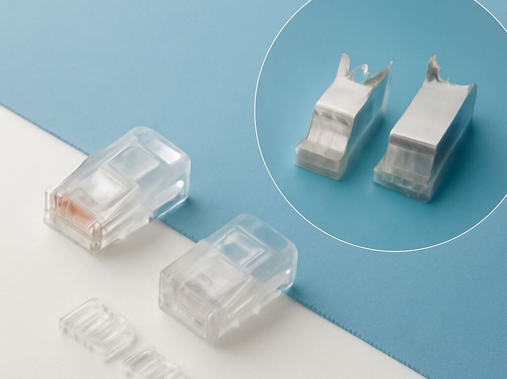
RJ45 vs Cat6: Wire Order and Shielded Cable Choices
The practical answer to rj45 vs cat6 is that the terms describe different parts of an Ethernet connection. RJ45 is commonly used as shorthand for an 8P8C modular connector, while Cat6 identifies the performance category of the cable and compatible connecting hardware. A Cat6 cable still needs suitable plugs, jacks, patch panels, and installation practices to deliver Cat6 channel performance.
Use the rj45 wire order consistently with either T568A or T568B, and select shielded or unshielded construction according to the interference environment and the available grounding path. Shielding is not an automatic upgrade: an incomplete shield system can add cost without providing reliable noise protection.
RJ45 vs Cat6: Connector, Cable, and Channel Ratings
RJ45 and 8P8C: Connector shorthand, not a cable rating
In everyday networking language, RJ45 usually means the eight-position, eight-contact modular plug or jack used for Ethernet. The more precise physical description is 8P8C: eight positions and eight contacts. RJ45 is technically a registered-jack interface designation, but the terms are commonly used interchangeably in Ethernet product listings.
Neither RJ45 nor 8P8C identifies cable performance. A connector can be used with several Ethernet cable categories, provided the connector is designed and rated for the cable and transmission requirements. The connector’s contact layout also does not determine whether a link is Cat5e, Cat6, or Cat6A.
Cat6 cable and category-rated connecting hardware
Cat6 is a balanced twisted-pair cable category with transmission requirements up to 250 MHz. It is commonly used for 1 Gb/s Ethernet over a 100 m channel. Some 10 Gb/s applications can run over Cat6 for shorter distances, but the result depends on channel length, crosstalk, component performance, and installation quality.
Category performance applies to more than the horizontal cable. Cat6-rated jacks, patch panels, plugs, and patch cords are needed when a Cat6 channel is required. A Cat6 cable terminated with lower-category hardware is limited by that hardware. Conversely, higher-rated hardware does not make a lower-category cable perform as Cat6.
Plug selection must also match the cable’s physical construction. Solid-conductor permanent cable and stranded patch cable may require different plug contacts. Conductor diameter, insulation diameter, pair geometry, conductor arrangement, and shield construction affect whether a termination is reliable and category compliant.
How the complete channel determines performance
An Ethernet channel normally includes the permanent link, patch cords, jacks, plugs, and patch panels between active equipment. A common structured-cabling design allows up to 90 m of permanent link and up to 10 m of patch cords, although the applicable design and testing limits should be followed for the installation.
The weakest component or termination can reduce the channel’s usable performance. Poor untwisting at a jack, excessive bend force, damaged cable, an incompatible plug, or an incorrectly seated contact can increase crosstalk and return loss even when the cable reel is properly labeled Cat6. Category labels therefore describe a system of compatible components, not just the jacket printed on the cable.
T568A and T568B: RJ45 Wire Order
T568A pin order: white/green, green, white/orange, blue, white/blue, orange, white/brown, brown
The T568A pinout places the conductors on pins 1 through 8 in this order:
- White/green
- Green
- White/orange
- Blue
- White/blue
- Orange
- White/brown
- Brown
T568B pin order: white/orange, orange, white/green, blue, white/blue, green, white/brown, brown
The T568B pinout places the conductors on pins 1 through 8 in this order:
- White/orange
- Orange
- White/green
- Blue
- White/blue
- Green
- White/brown
- Brown
T568B swaps the orange and green pairs compared with T568A. Both standards support normal Ethernet operation when the pairs are maintained correctly and the same standard is used at both ends. The blue pair remains on pins 4 and 5, and the brown pair remains on pins 7 and 8 in both pinouts.
Choose one wiring standard and use it end to end
For a standard straight-through cable or permanent link, terminate both ends with the same scheme: T568A to T568A or T568B to T568B. The important rule in the rj45 wire order is not which of these two standards is chosen, but that the selected standard is applied consistently across jacks, patch panels, and plugs.
Using T568A on one end and T568B on the other creates a crossover arrangement. Modern network equipment commonly supports automatic transmit-receive correction, so a crossover may still work, but it is not the normal choice for structured cabling. Mixed standards can also make troubleshooting and future changes harder.
Keep each twisted pair together until the termination point and untwist only as much as the connector manufacturer permits. Correct color order alone does not prevent split pairs, in which conductors from different pairs are placed in the expected pin positions. A cable tester that checks pair identity is needed to detect that fault.
Shielded vs Unshielded Cable: Choose by Environment and Grounding
Compare interference, shield types, size, cost, and installation
The choice in shielded vs unshielded cable should begin with the electromagnetic environment and the complete installation path:
- Unshielded twisted pair: U/UTP has no overall metallic shield. It is usually smaller, more flexible, less expensive, and simpler to terminate. It is the practical choice for most offices, homes, classrooms, and other locations with ordinary cable routing and adequate separation from electrical noise sources.
- Shielded twisted pair: Shielded designs use metallic foil, braid, or both. F/UTP has an overall foil shield around unshielded pairs; S/FTP typically uses an overall braid plus individual foil shields around the pairs. Other constructions combine these elements. The exact designation should be checked on the cable and hardware.
- High-interference environments: Shielding can reduce coupled noise near variable-frequency drives, large motors, industrial machinery, high-current conductors, radio equipment, and dense electrical infrastructure. Cable routing, separation, bonding, and termination quality still affect the result.
Shielded components are generally larger and less flexible. They can require more rack space, larger bend radii, compatible cable glands or plugs, and more time during termination. The cable, jacks, patch panels, patch cords, and equipment bonding path also cost more than comparable unshielded components.
Shielding should not be selected merely because it appears more robust. An unshielded system is often more reliable than a shielded system installed with incompatible parts or an incomplete bonding path. In a typical low-noise building, U/UTP reduces installation complexity. In a documented industrial or high-EMI design, a fully compatible shielded channel may provide better noise control.
Ground the shield and preserve component continuity
A shield works as part of a continuous conductive system. A shielded cable connected to an unshielded jack, ordinary patch panel, or unshielded patch cord has a break in that path. The metal parts of shielded plugs and jacks must contact the cable shield, and shielded patch panels must maintain continuity through the rack or bonding hardware.
The shielded channel must be bonded to the site’s grounding and bonding system according to the applicable electrical and cabling practices. The exact connection depends on the equipment, rack, patch-panel design, and local requirements. A shield should not be attached to an arbitrary nearby object, and a plan that grounds only one isolated cable end does not provide the same controlled continuity as a properly bonded channel.
Check the manufacturer’s compatibility requirements for drain wires, foil orientation, termination clamps, and shielded modular plugs. Avoid damaging the foil or braid during stripping, and preserve the specified bend radius. A shield that is electrically discontinuous, poorly clamped, or terminated with nonmatching hardware may provide unpredictable protection and can complicate fault diagnosis.
Match Components, Grounding, and Test the Channel
Match cable, plugs, jacks, and patch panels by category
Build the channel from components with the required category rating. For a Cat6 installation, that normally means Cat6 horizontal cable, Cat6 jacks, Cat6 patch panels, and patch cords or plugs rated for the intended use. Confirm that each plug accepts the cable’s conductor type and size; a field-terminated plug intended for stranded patch cable may not be suitable for solid horizontal cable.
For a shielded installation, match the shield construction as well as the category. Use shielded cable with shielded jacks, patch panels, plugs, and patch cords, and provide the bonding hardware specified for the rack or enclosure. For U/UTP, use unshielded components unless a particular design requires otherwise. Mixing constructions can leave the channel without continuous shielding.
Verify pinout, continuity, grounding, and channel certification
Test every completed link before it is placed into service. A basic wiremap test should confirm:
- Pin-to-pin continuity from end to end
- Correct T568A-to-T568A or T568B-to-T568B arrangement
- No opens, shorts, reversals, or crossed conductors
- No split pairs, which a simple continuity check may miss
For a Cat6 performance claim, use a calibrated certification tester appropriate to the channel class. Certification testing evaluates characteristics such as insertion loss, return loss, propagation delay, and near-end or far-end crosstalk against the applicable limits. A link light or basic continuity tester can show that conductors are connected, but it cannot prove category performance.
For shielded cabling, also verify shield continuity across every plug, jack, patch panel, and patch cord, then confirm the intended rack and equipment bonding path. Resolve failed wiremap, category, or shield tests before closing the installation; replacing a short patch cord or correcting one termination is usually easier than diagnosing intermittent performance after the channel is in use.