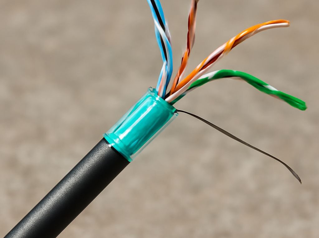
PoE Ethernet Cable and Fiber Backbones for Outdoor Networks
Use a PoE Ethernet cable for the final outdoor link when a camera, access point, intercom, or sensor needs both data and power. Use fiber for the backbone when the route exceeds the 100-meter copper channel limit, crosses between buildings, faces significant lightning exposure, or requires higher bandwidth with electrical isolation.
A dependable design separates the powered copper endpoint from the optical backbone. The network typically runs from a PoE switch through fiber to a remote enclosure, then changes back to copper for the short connection that powers the endpoint.
PoE Ethernet cable: match endpoint power, speed, and distance
Start with the endpoint’s required power, Ethernet speed, and cable distance. PoE standard, switch capacity, cable construction, and installation conditions all affect whether the endpoint will operate reliably.
- IEEE 802.3af, PoE: supplies up to 15.4 watts from the power-sourcing equipment, with approximately 12.95 watts available to the powered device after cable losses.
- IEEE 802.3at, PoE+: supplies up to 30 watts, with approximately 25.5 watts available at the endpoint.
- IEEE 802.3bt Type 3: can provide up to 60 watts at the source and approximately 51 watts to the device.
- IEEE 802.3bt Type 4: can provide up to 90 watts or more at the source, depending on the equipment, with the usable endpoint budget lower than the source rating.
The switch or injector must have enough total PoE budget for all connected devices. A switch with a 370-watt budget, for example, cannot necessarily run twenty-four 30-watt devices at their maximum draw. Allowance is also needed for startup loads, cold-weather operation, cable loss, and future endpoints. The powered device’s data sheet and the switch’s per-port and total budgets should be checked together.
A standard copper Ethernet channel is limited to 100 meters, normally consisting of a 90-meter permanent link and up to 10 meters of patch cords. The limit applies to the complete channel, not just the cable pulled through conduit. A long route should therefore use fiber for the backbone and reserve copper for the final PoE segment.
Speed requirements also influence the choice. Gigabit PoE commonly uses all four twisted pairs, while newer equipment may require 2.5GbE, 5GbE, or 10GbE. The cable, jacks, patch cords, and termination hardware should share the required category and performance. Higher-power PoE creates more heating in cable bundles, so large installations should follow the cable manufacturer’s bundle-size and temperature guidance.
Choose a Cat6 outdoor cable for powered endpoints
A Cat6 outdoor cable should be selected for its construction and environmental rating, not merely because a link works during a short indoor-style test. Outdoor cable needs a jacket rated for the actual exposure and a conductor design suitable for permanent installation.
For fixed PoE runs, solid bare-copper conductors are generally preferred. They provide predictable resistance, termination performance, and power delivery. Copper-clad aluminum cable should not be substituted for compliant solid copper Ethernet cable; its higher resistance can reduce PoE performance and create unacceptable heating or voltage drop. A 23 AWG solid conductor is common for robust permanent Cat6 installations, but the approved conductor size should match the connector, pathway, bend radius, and PoE design.
Choose the jacket according to the route:
- UV-resistant outdoor jacket: appropriate for exposed aerial or surface runs where sunlight can degrade ordinary indoor PVC.
- Wet-location or water-blocking construction: suitable for damp pathways, conduit with condensation, and locations where moisture can migrate along the cable.
- Direct-burial rating: required when the cable is placed directly in soil. A standard indoor cable inside a shallow trench is not automatically a direct-burial installation.
- Outdoor-rated cable in conduit: useful where mechanical protection, replacement access, or a controlled pathway is needed. The cable must still be rated for moisture and temperature conditions inside the conduit.
Direct burial and conduit solve different problems. Direct-burial cable is built for soil contact and should be installed at the specified depth with protection from rocks, roots, and future excavation. Conduit provides a replaceable pathway and additional mechanical protection, but it must be sealed or drained appropriately. Water can collect inside outdoor conduit, so conduit alone does not make indoor cable suitable for a wet route.
At buildings and exposed equipment, consider the cable’s surge and grounding arrangement. Shielded Cat6 can help with electromagnetic interference when its connectors, patch panels, and equipment are bonded correctly. A shield that is left floating or bonded inconsistently does not provide the intended protection. Ethernet surge protectors rated for the applicable PoE standard can be installed at exposed transitions, with bonding connected to the site grounding system according to local electrical requirements.
Keep outdoor copper runs away from avoidable lightning paths and do not route them between buildings when fiber can provide the link. Copper entering a camera pole, gate, or detached building can conduct a surge toward network equipment. A short, protected PoE copper segment after a fiber termination is usually easier to protect than a long copper interbuilding run.
Choose bulk fiber optic cable for the backbone
Bulk fiber optic cable is the practical choice for a backbone that needs distance, bandwidth, or electrical isolation. Fiber does not carry PoE power. It carries optical data only, so the remote end must include local power for a switch, media converter, or endpoint-power device before copper PoE can be delivered.
Select fiber mode according to the transceivers and distance:
- Multimode OM3 or OM4: suitable for many campus, plant, and site links over relatively short distances. OM4 generally supports more optical headroom than OM3, but the transceiver specification sets the usable distance.
- Single-mode OS2: the usual choice for longer building, campus, and utility routes. It supports long distances with the correct optics and avoids replacing the cable when the network later moves to a longer-reach link.
A duplex link normally needs two fiber strands: one for transmit and one for receive. A four-, six-, or twelve-strand cable can provide spare capacity for repairs, additional links, or future upgrades. Strand count should account for the number of network paths, not only the first switch connection.
Jacket and armor should match the installation. Outdoor loose-tube cable is commonly used in ducts and pathways because it tolerates moisture and temperature changes. Direct-burial fiber needs a direct-burial rating and the specified water-blocking construction. Armored cable can add rodent and crush resistance, while dielectric armor avoids introducing a conductive path between buildings. Metallic armor may require bonding and grounding at the termination points; the cable manufacturer’s construction details and local electrical rules control that decision.
Plan the termination method before purchasing the cable. LC connectors are common for switch and SFP connections, while ruggedized field systems may use sealed connector assemblies. Field termination can be appropriate for small jobs, but fusion-spliced pigtails usually provide more repeatable performance on permanent outdoor routes. Splice trays and panels need enough room for bend-radius control, identification, and future service.
Transceivers must match fiber mode, wavelength, connector type, speed, and reach. A single-mode optic connected to multimode fiber, or a 10Gb optic used with a 1Gb interface, will not create a valid design simply because the connectors fit. Where a switch has no fiber slot, a media converter can change copper Ethernet to fiber, but the converter needs a suitable power source and should be installed in a weather-protected enclosure.
Provide service slack at both ends and at planned splice points. Slack should be stored without exceeding the cable’s minimum bend radius, and the enclosure should have enough space for the specified fiber loops. Avoid pulling on connectors, sharply bending the cable at the entry gland, or leaving unprotected splice closures exposed to standing water.
Transition, protect, and test the complete route
The most reliable arrangement places the fiber-to-copper transition inside a properly rated enclosure near the remote endpoint. The sequence is typically: core switch, optical transceiver or media converter, fiber backbone, remote optical transceiver or media converter, local Ethernet switch or PoE injector, and short outdoor copper cable to the powered device.
The remote enclosure needs more than a weather-resistant label. It should provide cable glands or sealed entries, drainage or condensation control, bend-radius space, strain relief, equipment mounting, and a power arrangement suitable for the switch or injector. If the endpoint is at a pole or gate, the enclosure should keep the PoE electronics away from direct spray and allow service without disturbing the fiber splice.
Use fiber to isolate separate buildings or exposed structures whenever practical. A dielectric fiber route does not conduct a lightning surge between sites. The copper section at each end still needs attention: keep it short, use outdoor-rated cable, bond metallic hardware correctly, and install compatible surge protection where exposure warrants it. Surge protectors should be bonded to the same grounding system used by the protected equipment; a long or improvised grounding lead can reduce protection effectiveness.
Grounding requirements depend on the cable and equipment. Fiber itself is nonconductive, but metallic armor, messenger wire, shielded copper, racks, and enclosure hardware may require bonding. Grounding should follow the equipment instructions and applicable electrical code rather than relying on a separate ground rod with no bonding path to the building system.
Test the complete route in stages:
- Inspect the installation: confirm jacket ratings, pathway separation, bend radius, entry seals, labeling, strain relief, and termination polarity.
- Certify copper: use a suitable Cat6 tester for wire map, length, insertion loss, return loss, crosstalk, and other required parameters. Test the installed channel, including patch cords where they are part of the link.
- Verify PoE: connect the intended endpoint or a compatible load tester and confirm negotiation, delivered voltage, startup behavior, data rate, and operation at the expected cable length.
- Test fiber: inspect and clean every connector, then measure optical insertion loss against the transceiver and link budget. An OTDR can help locate high-loss events, bad splices, excessive bends, or damaged sections on longer routes.
- Run the live path: confirm the remote switch, camera, access point, or sensor remains stable under traffic and power load. Check the switch’s PoE budget and logs after all endpoints are connected.
A route is ready when the outdoor copper passes its category test, the optical loss remains within the transceiver budget, the remote equipment receives stable local power, and the powered endpoint operates at the planned speed without link drops or PoE faults.