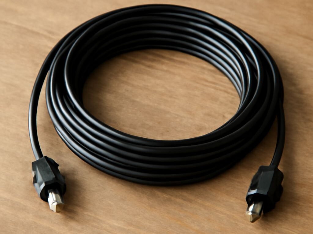
USB to Ethernet Cable: Choose an Active Adapter and Cat6 Link
A USB to Ethernet cable delivers a wired network connection only when it contains active adapter electronics. A passive USB cable merely carries USB signals and cannot convert them into Ethernet. For a reliable link, match the adapter’s USB connector and generation to the computer, confirm operating-system and driver support, then choose an Ethernet speed the USB bus can sustain.
Use a Cat6 shielded cable when electrical noise, long parallel cable runs, or industrial equipment could disturb an unshielded link. Shielding does not increase Ethernet speed by itself, and it works correctly only when the plugs, jacks, cable, and grounding path are compatible.
USB to Ethernet Cable Types: Choose an Active Adapter
Why a simple USB cable cannot provide Ethernet
A USB Ethernet adapter contains a USB controller, an Ethernet network interface controller, a physical-layer transceiver, and an RJ45 port. The electronics translate USB data into Ethernet frames and expose the connection to the operating system as a network interface.
A passive USB-A-to-USB-C or USB-C-to-USB-C lead has none of those components. It can connect or charge USB devices, but it cannot create a network port. Product descriptions that use “USB Ethernet cable” can therefore be misleading. The adapter housing should include an Ethernet socket and, normally, link or activity indicators.
Most adapters are bus-powered. A compact unit draws power from the USB port, while a dock may share that power with HDMI, storage, card readers, and charging functions. If the adapter repeatedly disconnects under load, connect it directly to the computer instead of an unpowered hub, or use a powered dock. A 2.5GbE or faster adapter can place more demand on the USB bus and power budget than a basic 100MbE model.
USB connectors, generations, drivers, power, chipsets, and link LEDs
Check the physical connector first:
- USB-A: Common on desktop computers and older laptops. The connector shape alone does not identify the USB generation.
- USB-C: Reversible and common on current laptops, tablets, and docks. USB-C also does not guarantee USB 3.x or USB4; the host port’s specification determines the available bandwidth.
- USB micro-B: Found on some older adapters and accessories. It is less convenient and should be checked for both data support and mechanical durability.
Next, identify the adapter’s USB generation and Ethernet port rating. A USB 3.x adapter with a USB-A plug may fall back to USB 2.0 when attached to an older port. A USB-C adapter can also fall back if connected through a USB 2.0-only cable, hub, or dock.
Driver support is equally important. Windows, macOS, Linux, and ChromeOS may recognize common chipsets automatically, but support varies by operating-system version and chipset revision. Common families include Realtek RTL8153 for 1GbE and RTL8156 for 2.5GbE, plus ASIX controllers in some older products. The chipset is not a guarantee of compatibility, so the manufacturer’s driver page and supported OS list should be checked before purchase. Corporate or managed computers may also restrict third-party kernel or network drivers.
Link LEDs provide a quick hardware check. One light may indicate a detected link, while another shows activity or negotiated speed, but colors and meanings vary by model. No light usually points to a disconnected cable, inactive switch port, missing driver, insufficient power, or failed adapter. The operating system’s network settings should confirm the negotiated speed rather than relying on LED color alone.
How to Compare Ethernet Adapters by Speed and OS Support
Match USB 2.0, USB 3.x, or USB4 to the Ethernet rate
The USB interface must have enough practical bandwidth for the Ethernet interface:
- USB 2.0 to 100MbE: A suitable, inexpensive combination for basic broadband, office access, and older switches.
- USB 2.0 to 1GbE: It can function, but USB overhead and other bus traffic usually prevent full gigabit throughput. Actual performance often falls well below 1Gbps.
- USB 3.0 or USB 3.2 Gen 1 to 1GbE: Provides enough bandwidth for a normal gigabit link, subject to the computer, adapter, and network equipment.
- USB 3.x to 2.5GbE or 5GbE: The usual match for multi-gigabit adapters. Performance depends on whether the host port, chipset, cable, switch, and computer can sustain the rate.
- USB4 or Thunderbolt-compatible hardware: Offers substantial headroom, but the adapter must explicitly support the required Ethernet speed. A fast USB port does not automatically make a 10GbE adapter.
Ethernet rates are negotiated independently from USB rates. A 2.5GbE adapter plugged into a gigabit switch will correctly establish a 1Gbps Ethernet link, while a 1GbE adapter cannot exceed 1Gbps even when connected to a 10GbE switch. The slowest component is the bottleneck: USB port, adapter, switch, router, cable, storage device, or remote server.
USB bus sharing can also reduce results. A dock transferring data to an external SSD while running Ethernet may divide available bandwidth among several devices. For a dedicated wired link, a direct connection is generally easier to diagnose than a multifunction dock.
Full-duplex negotiation and the real network bottleneck
Modern Ethernet normally uses auto-negotiation to select speed and full-duplex operation. Both ends exchange their capabilities, such as 1000BASE-T full duplex or 2.5GBASE-T. The switch and adapter should show the same result in their status panels.
Do not force one end to a fixed speed or half-duplex setting unless a specific legacy device requires it. A duplex mismatch can cause collisions, retransmissions, low throughput, and inconsistent performance. If the link negotiates at 100Mbps instead of 1Gbps, inspect the cable and terminations first; gigabit Ethernet requires all four twisted pairs, while 10/100 Ethernet can operate on only two pairs.
For internet access, the broadband service may be slower than the Ethernet link. For local file transfers, the storage devices and server may be the limiting factors. A fast adapter is worthwhile when the local switch, NAS, workstation, or internet service also supports the higher rate.
When a Cat6 Shielded Cable Is Worth Using
Shield types, compatible plugs and jacks, and grounding
A Cat6 shielded cable adds a conductive barrier around the twisted pairs or around the entire cable. Common constructions include:
- F/UTP: An overall foil shield surrounds unshielded twisted pairs.
- U/FTP: Each pair has foil shielding, without an overall braid or foil.
- S/FTP: Each pair is foil-shielded and an overall braid provides additional protection.
Shielding is useful near motors, fluorescent lighting, radio transmitters, industrial machinery, power distribution equipment, or dense bundles carrying electrical power. It is often unnecessary for a short home or office run routed away from noise sources. An unshielded Cat6 cable can already deliver gigabit and many multi-gigabit links at standard distances.
The shield must be continuous through the complete channel. Use shielded RJ45 plugs with a metal strain-relief shell, shielded keystone jacks, and shielded patch panels when those components are part of the run. A shielded cable connected to ordinary plastic plugs may still carry Ethernet, but its shielding path is interrupted. Plugs must also match the conductor type: plugs designed for solid conductors may not terminate stranded patch cable reliably, and vice versa.
Grounding occurs through compatible shielded equipment and the network hardware’s protective-earth path. Do not attach a random wire to a cable shield or assume that a shielded cable must be grounded at a separate household ground point. Poorly assembled shield connections can introduce noise rather than reduce it. Where different buildings or electrical systems are involved, a qualified installer should determine the appropriate bonding and isolation method.
Environment, length, termination, and wire-map checks
Cat6 supports 1GbE over a channel up to 100 metres under standard installation conditions. 10GbE over Cat6 is generally limited to shorter distances, commonly up to about 55 metres depending on cable quality, bundle size, and interference. The cable category does not override the limits of the Ethernet standard or the adapter.
Keep the cable within its rated temperature and bend radius. Avoid crushing it under furniture, sharply folding it behind a rack, or running it tightly alongside power cables for long distances. Shielding cannot compensate for damaged pairs, excessive untwist, or poor connector workmanship.
For field termination, preserve the pair twists as close to the plug or jack as the termination instructions allow. Use the same wiring standard at both ends, either T568A or T568B. A normal straight-through patch cable uses the same standard on both ends; mixing standards creates a crossover arrangement. Modern equipment often corrects for this, but consistent termination is easier to verify.
A cable tester should confirm the wire map from pins 1 through 8, pair order, continuity, and shorts. For a shielded installation, the tester should also check shield continuity where applicable. A cable that passes continuity but has split pairs can still fail gigabit negotiation, so a basic pin-light tester is less informative than a tester that identifies pair mapping and performance category.
Connect, Negotiate, and Test the Wired Link
Connect the adapter and verify link indicators
- Install the adapter’s driver if the operating system does not detect it automatically. Restart the computer if the driver installer requests it.
- Connect the adapter directly to the selected USB port. Avoid a USB 2.0 hub when testing a gigabit or multi-gigabit adapter.
- Attach the Cat6 cable to the adapter and to a powered switch, router, or wall jack.
- Wait several seconds for auto-negotiation. Check the adapter LED, switch-port LED, and operating-system network status.
- Confirm that the reported Ethernet speed and duplex mode match the expected connection, such as 1Gbps full duplex or 2.5Gbps full duplex.
If there is no link, test another switch port and another known-good cable. If the link is present but limited to 100Mbps, replace or retest the cable, inspect both plugs, and check for a damaged pair. If the adapter disappears from the operating system, reinstall the driver, remove other USB devices from the same hub, and test the adapter on a second computer.
Run wire-map and throughput tests
Run a wire-map test before blaming the adapter for poor performance. The test should show all eight conductors in the correct pairs, with no opens, shorts, reversals, or split pairs. For a permanent run, test the installed channel from the wall jack at one end to the patch-panel or equipment jack at the other.
For throughput, use a local test rather than an internet speed test. The iperf3 utility can measure traffic between two computers connected to the same switch. Run one system as the server and the other as the client, then compare the result with the negotiated Ethernet rate. A healthy gigabit link commonly reports roughly 900 to 950Mbps of TCP throughput, while a 2.5GbE link may report approximately 2.2 to 2.4Gbps when the computers and storage are fast enough. Results vary with CPU load, protocol overhead, and test settings.
Use the operating-system interface counters during the test. Excessive errors, dropped packets, retransmissions, or rapidly increasing CRC counts indicate a physical-layer problem. If counters remain clean but throughput is low, check the USB generation, shared hub bandwidth, CPU load, disk speed, server capability, and switch configuration before replacing the Cat6 cable.