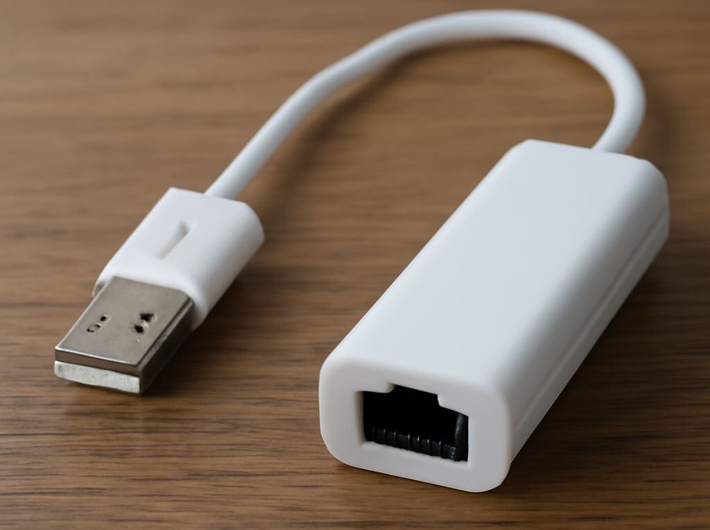
USB-to-Ethernet Adapter Setup: T568B RJ45 Wiring and Testing
A USB-to-Ethernet adapter adds a wired network interface to a computer, tablet, or other host that lacks a suitable Ethernet port. Choose it by USB connector and generation, Ethernet speed, chipset and driver support, power requirements, and MAC-address behavior. Then connect it to a properly terminated T568B cable and verify the physical link, DHCP assignment, negotiated speed, and actual throughput.
The adapter contains active electronics that translate USB data into Ethernet frames. The RJ45 cable is passive: it carries the signal but cannot convert USB on its own. Keeping those two functions separate makes setup and troubleshooting more reliable.
How to choose a USB-to-Ethernet adapter
Check the USB connector and generation
Start with the host-side connector. USB-A adapters suit many desktops, laptops, and older docking stations, while USB-C adapters suit newer laptops, tablets, and phones. A USB-C plug describes the connector shape, not necessarily the data speed, so the host port and adapter specifications both need checking.
USB 2.0 has a 480 Mb/s theoretical bus rate and can support 10/100 Ethernet easily. It may also operate a Gigabit Ethernet adapter, but the USB bus, system overhead, and other devices can limit practical throughput. USB 3.x is the better match for Gigabit Ethernet and is generally required to make full use of 2.5 Gigabit Ethernet. A USB 3 adapter connected through a USB 2 port will normally fall back to the slower generation.
Check whether the adapter requires a USB-C port with specific features. Some USB-C ports support only USB 2.0 data, while others support USB 3.x or faster. A passive USB-C shape adapter cannot add a missing USB data capability.
Match Ethernet speed, chipset, driver support, power, and MAC address
Match the Ethernet side to the network. A 10/100 adapter is sufficient for older equipment, but a 10/100/1000 adapter is the practical choice for most wired networks. A 2.5GbE model is useful only when the computer, switch or router, and cable can support that rate. The adapter will normally negotiate down when connected to a slower port.
Chipset support matters because the operating system needs a compatible driver. Common families include Realtek, ASIX, and USB-native Ethernet controllers, but the chipset name alone does not guarantee compatibility. Check the manufacturer’s operating-system list, driver delivery method, and support for features needed in the environment, such as VLAN tagging, PXE boot, Wake-on-LAN, or macOS and Linux support. An adapter that powers on but has no recognized network interface may have a driver or compatibility problem rather than a cable problem.
Most compact adapters are bus-powered. A simple Gigabit model usually draws modest power, while multiport docks and 2.5GbE adapters can place more demand on the USB port. If the adapter disconnects under load, try a different port, remove an unpowered hub, or use a dock with external power. For a phone or tablet, verify that the host supports USB-OTG or equivalent host mode.
Each adapter generally presents its own MAC address to the network. This can affect DHCP reservations, access-control lists, captive portals, and network registration. Some models use a fixed hardware address; others allow software changes or may expose a different address after replacement. Record the address shown by the operating system if a network administrator has tied access to a specific device.
How a USB-to-Ethernet converter works
Why the adapter needs active electronics
A USB-to-Ethernet converter contains a USB interface controller, an Ethernet media-access controller, and a physical-layer transceiver. The USB controller communicates with the host, while the Ethernet circuitry negotiates link speed and encodes data for the twisted-pair cable. The device driver connects those functions to the operating system’s network stack.
A passive cable has none of these components. It contains copper conductors arranged in twisted pairs and terminated in modular plugs. Such a cable can connect an Ethernet port to a switch or connect an adapter to a network outlet, but it cannot change a USB signal into Ethernet. Any product described only as a USB cable with an RJ45 plug should be treated cautiously unless it includes an electronic adapter housing and documented chipset.
Separate adapter compatibility from passive cable wiring
Test the adapter without assuming the cable is at fault. First confirm that the operating system detects a new Ethernet interface when the adapter is connected. If it does not appear, investigate the USB port, driver, chipset, power, and operating-system support. If the interface appears but there is no link after a cable is attached, investigate the RJ45 termination, cable pairs, switch port, and Ethernet negotiation separately.
The adapter and cable also have different speed limits. A correctly wired cable may still show only 100 Mb/s because the adapter or switch is limited to Fast Ethernet. Conversely, a Gigabit adapter cannot negotiate Gigabit reliably through a damaged cable or a termination with a split pair.
T568B RJ45 wiring: color order and plug orientation
Read pins 1–8 with the contacts facing you and latch away
For a standard RJ45 plug, hold the plug with the gold contacts facing you and the locking latch facing away. With the cable entering from the rear, pin 1 is on the left and pin 8 is on the right. Arrange the conductors left to right in this T568B order:
- Pin 1: white/orange
- Pin 2: orange
- Pin 3: white/green
- Pin 4: blue
- Pin 5: white/blue
- Pin 6: green
- Pin 7: white/brown
- Pin 8: brown
The resulting pair assignments are orange on pins 1–2, green on pins 3 and 6, blue on pins 4–5, and brown on pins 7–8. The green pair is separated around the blue pair in the pin sequence; that is normal for T568B and is why color order should be checked rather than guessed.
For an ordinary straight-through patch cable, terminate both ends with the same T568B order. A cable with T568B at one end and T568A at the other is a crossover cable. Modern Ethernet ports commonly support auto-MDI-X, but matching T568B at both ends avoids unnecessary compatibility issues and is the usual patch-cable convention.
When terminating a cable, keep each twisted pair together as close to the plug contacts as the connector design allows. Untwisting too much can weaken signal quality, especially at Gigabit and faster rates. Ensure every conductor reaches the front of the plug, the outer jacket is captured by the strain relief, and the contacts are fully crimped.
Run a wire-map and continuity check
Use a cable tester with a remote unit before connecting a newly terminated cable to network equipment. A correct wire-map test should report pins 1 through 8 in the same order at both ends. Continuity alone is not enough: a cable can have all eight conductors connected and still contain a reversal, short, open, or split pair.
- Open: one conductor is not making contact.
- Short: conductors are electrically connected where they should not be.
- Reversal: the two conductors in a pair are presented in the wrong sequence.
- Split pair: continuity appears correct by pin number, but conductors from different twisted pairs have been combined, causing poor Ethernet performance.
For a known-good factory cable, a tester can confirm the basic wire map. For a field-terminated cable, inspect the plug again if the tester reports anything other than a straight 1-to-1 map. Do not rely on link LEDs as the only cable test.
Connect and verify the network link
Check link LEDs, interface status, and DHCP
- Install the adapter driver if the operating system does not provide one automatically, then restart the host if the installer requests it.
- Connect the adapter directly to the host or to a powered dock. Confirm that the Ethernet interface appears in the operating system’s network settings.
- Attach the tested T568B cable to the adapter and to a known-good switch or router port. Check the adapter and switch link LEDs. A steady or flashing LED normally indicates physical link and traffic, although LED meanings vary by model.
- Open the interface details and confirm that it is enabled and not blocked by airplane mode, a disabled profile, or a manually assigned configuration.
- Request an address through DHCP. The interface should receive an IP address, subnet mask or prefix, default gateway, and DNS settings. A self-assigned address, such as a 169.254.x.x address on many IPv4 systems, usually indicates that DHCP did not complete; it does not prove that the adapter is defective.
- Test the local gateway first, then another device on the same network. This separates a local Ethernet problem from an internet, DNS, or upstream routing problem.
Confirm negotiated speed and measure throughput
Check the interface’s negotiated link speed in the operating system or adapter utility. The expected result might be 100 Mb/s, 1.0 Gb/s, or 2.5 Gb/s, depending on the adapter, USB connection, switch port, and cable. The negotiated value is the connection rate between the adapter and network equipment, not a guarantee of internet speed or file-transfer performance.
If a Gigabit-capable setup negotiates only 100 Mb/s, inspect the cable’s wire map and pair condition first. Gigabit Ethernet requires all four twisted pairs, while 100 Mb/s can continue working with fewer pairs. Also test another switch port and confirm that the host is using a USB 3.x connection rather than a USB 2.0 port or hub.
Measure throughput on the local network with a tool such as iperf3 or with a controlled file transfer to a wired device. Use a known-fast server, allow for protocol overhead, and repeat the test in both directions when possible. A low result with a full-speed negotiated link points toward USB bus sharing, CPU load, driver behavior, switch congestion, or the test server. A low negotiated link points first toward cabling, port configuration, or physical-layer compatibility.