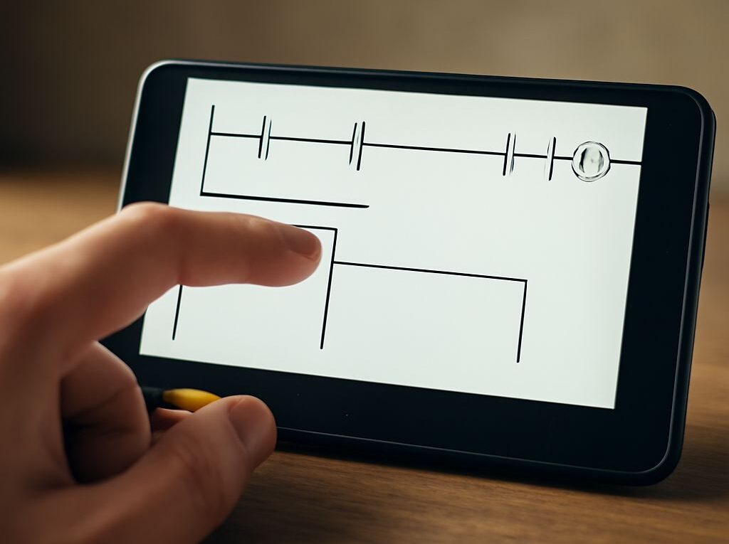
Ladder Logic Simulator: Free and Open-Source Options for Practice
A ladder logic simulator is useful when the goal is to practice contacts, coils, latches, timers, and fault responses without a physical controller. The best first choice depends on the desired result: PLC Fiddle offers the fastest browser-based exercise, OpenPLC provides an open-source PLC runtime path, and CODESYS offers the broadest IEC 61131-3 development environment. Beremiz and LDmicro are useful alternatives when file-based tools or microcontroller-oriented practice matter.
A free PLC simulator can show virtual inputs and outputs, but it may not reproduce a proprietary controller’s scan timing, I/O hardware, communication stack, or instruction behavior. The practice project below therefore emphasizes concepts that transfer across platforms: a sealed-in motor command, safety permissives, a fault indication, repeatable test states, and saved evidence.
Compare a ladder logic simulator: OpenPLC, CODESYS, Beremiz, and PLC Fiddle
The options differ mainly in what they execute and how much setup they require.
- OpenPLC is an open-source runtime and editor path for IEC 61131-3 programs. It is a strong choice for learners who want to see how a soft PLC executes a program on a general-purpose computer or small Linux device. OpenPLC commonly supports ladder logic, function block diagram, structured text, instruction list, and sequential function chart through its editor toolchain. Virtual variables can be tested directly, while Modbus TCP or serial connections can connect the runtime to external tools. Deployment and configuration require more work than a browser simulator.
- Beremiz is an open-source IEC 61131-3 development environment that can work with a soft runtime. It suits learners interested in project files, generated code, and the boundary between an editor and a runtime. Beremiz supports several IEC languages and can expose variables for observation, but its setup and documentation can feel less immediate for a first ladder exercise.
- PLC Fiddle is a browser-based ladder practice tool. It is suitable for quickly placing contacts, coils, timers, and other basic ladder elements, then toggling virtual inputs and observing outputs. It is usually the shortest route to a first exercise because there is no local runtime installation. Its focus is ladder learning rather than a complete controller, fieldbus, or hardware emulation environment.
- LDmicro is a ladder editor and simulator with a microcontroller-oriented workflow. It is useful for learning scan-based Boolean logic and for examining generated controller-oriented projects. Its target model is not identical to a commercial PLC, and its operating-system support and workflow are narrower than browser-based tools or larger IEC environments.
- CODESYS provides a broad IEC 61131-3 development system with ladder logic, function block diagram, structured text, sequential function chart, and related language options. Its simulation and online tools support watch windows, forcing, timers, analog variables, and industrial-style project organization. The development system may be free to download, while particular runtimes, targets, or device features can have separate licensing terms.
OpenPLC and Beremiz: open-source runtime paths
OpenPLC and Beremiz are better understood as runtime-oriented toolchains than as isolated teaching widgets. They can execute a cyclic control program and map variables to simulated or external I/O. That makes them useful for learning how a PLC project is built, compiled, deployed, and monitored. It also introduces configuration, target, and communication issues that are absent from a simple browser exercise.
PLC Fiddle and LDmicro: quick ladder-focused practice
PLC Fiddle is the most convenient option for a short, repeatable ladder lesson. LDmicro is more appropriate when a learner wants local project files and a microcontroller-related perspective. Neither should be treated as proof that a specific industrial controller will interpret every instruction or timing edge in exactly the same way.
CODESYS: broader IEC 61131-3 simulation
CODESYS is the strongest choice when ladder practice will expand into structured text, function blocks, analog processing, visualization, or protocol experiments. It provides more industrially familiar project structure, but the additional features create a steeper learning curve and can introduce licensing differences between the editor, simulator, and deployment target.
Open source PLC runtimes vs. teaching simulators
Languages, scan model, and virtual I/O: what is actually executed
A teaching simulator generally executes a simplified ladder model and provides switches, indicators, or bit controls as virtual I/O. An open-source PLC runtime executes a compiled or interpreted control program in a cyclic task. CODESYS can provide a similar soft-PLC experience, depending on the selected runtime.
- Languages: Ladder diagram is the most direct language for contact-and-coil practice. Function block diagram helps with reusable logic, structured text suits calculations and conditions, and sequential function chart suits step sequences. A project is more portable when it uses standard IEC instructions rather than vendor-specific blocks.
- Scan model: A conventional PLC typically reads inputs, evaluates logic from top to bottom, updates outputs, and repeats. Simulators may update values immediately when a control is clicked, use a periodic task, or provide a manual step mode. A visible result is therefore not automatically evidence of real-controller timing.
- Virtual I/O: Internal Boolean tags are enough for the motor exercise below. More advanced tools can map tags to virtual channels, operating-system interfaces, Modbus registers, or real devices. A mapped bit still does not reproduce electrical noise, contact bounce, voltage loss, or output module behavior.
Watch and force tools, timers, analog support, and protocols
Watch windows display live tag values and are valuable for checking intermediate conditions such as a safety permissive or timer-done bit. Force tools override an input or output for testing. Forces must be clearly removed after a test because they can hide the actual ladder result; a browser tool may offer only simple toggles rather than formal force management.
IEC timers such as TON, TOF, and TP are commonly available in OpenPLC, Beremiz, and CODESYS, while lightweight ladder tools may provide only selected timer types. Timer accuracy depends on task period, simulator clock behavior, and whether elapsed time is measured in real time or simulation steps.
Analog support is another dividing line. CODESYS and runtime-oriented tools can represent integers, real values, scaling, limits, and analog channels. Ladder-focused teaching tools often concentrate on Boolean I/O. Protocol support may include Modbus TCP or serial links in a runtime, but a local virtual bit is not equivalent to a tested network transaction with a field device.
How to choose a free PLC simulator for ladder practice
Check OS support, project files, documentation, and licensing
Choose the smallest tool that can execute the intended exercise, then check these criteria before investing time in setup:
- Operating system: Confirm whether the editor and runtime support Windows, Linux, macOS, or only a browser. A browser tool is convenient, but local tools are easier to archive independently.
- Project files: Check whether programs can be saved as readable project files, exported, or reopened without a service account. File-based work is useful for repeat testing and version control.
- Documentation: Look for clear explanations of scan order, timer bases, virtual I/O, force behavior, and supported instructions. A large instruction list is less useful than reliable behavioral documentation.
- Licensing: Separate open-source code from free-of-charge downloads. OpenPLC and Beremiz provide open-source paths; CODESYS has free development components but may use separate runtime or device licenses. PLC Fiddle and other hosted tools may use service-specific saving or usage terms.
- Observation tools: Prefer a watch list, visible rung states, single-cycle execution, or a clear way to record input and output values.
Choose for concept portability rather than proprietary hardware equivalence
For a first exercise, PLC Fiddle is the fastest choice. OpenPLC is the better choice when an open-source PLC runtime, local files, and external I/O experiments are important. CODESYS is preferable for broader IEC practice, analog work, and industrial-style monitoring. Beremiz suits learners who want an open toolchain, while LDmicro suits ladder practice connected to microcontroller targets.
Portability improves when the project uses named Boolean tags, standard contacts and coils, IEC timers, explicit safety conditions, and a documented test sequence. It decreases when the project depends on vendor-specific motion blocks, high-speed tasks, retentive memory defaults, special edge instructions, or undocumented system variables.
Build and test a repeatable motor-starter project
Requirements, tags, ladder logic, and initial state
Build a small motor starter with a momentary start button, a maintained stop circuit, an emergency-stop status, an overload status, and three outputs. Use internal tags if the simulator has no physical I/O panel.
- Start_PB, BOOL: momentary start pushbutton.
- Stop_OK, BOOL: true when the stop circuit is healthy; false when Stop is pressed.
- EStop_OK, BOOL: true when the emergency stop is released and healthy.
- Overload_OK, BOOL: true when the overload has not tripped.
- Motor_Run, BOOL: motor command output.
- Run_Lamp, BOOL: running indicator.
- Fault_Lamp, BOOL: abnormal-condition indicator.
Set the initial state to Start_PB = false, Stop_OK = true, EStop_OK = true, Overload_OK = true, Motor_Run = false, Run_Lamp = false, and Fault_Lamp = false.
- Motor rung: Place normally open contacts for Stop_OK, EStop_OK, and Overload_OK in series. Add a parallel branch containing Start_PB and a normally open Motor_Run seal-in contact. Drive the Motor_Run coil. In Boolean form: Motor_Run = Stop_OK AND EStop_OK AND Overload_OK AND (Start_PB OR Motor_Run).
- Run indicator: Use a normally open Motor_Run contact to drive Run_Lamp.
- Fault indicator: Use normally closed contacts for EStop_OK and Overload_OK in parallel to drive Fault_Lamp. The lamp turns on when either status becomes false.
In a tool with IEC timer support, an optional extension is a two-second TON named Start_Delay. Place Start_Delay.Q in the start branch so the motor starts only after Start_PB remains true for two seconds. Record whether the simulator measures that interval in wall-clock time or scan steps.
Test table with expected outputs, abnormal inputs, and stop behavior
Run each test from a known state. Record the input settings before execution and the resulting output values after at least one scan.
- Initial state: Keep all healthy statuses true and Start_PB false. Expected result: Motor_Run, Run_Lamp, and Fault_Lamp are false.
- Start and release: Set Start_PB true for one scan, then return it to false. Expected result: Motor_Run becomes true and remains true through the seal-in contact; Run_Lamp is true and Fault_Lamp is false.
- Normal stop: Set Stop_OK false while the motor is running. Expected result: Motor_Run and Run_Lamp turn false on the next executed scan. Restore Stop_OK to true; the motor must remain off until a new start command.
- Emergency stop: Start the motor, then set EStop_OK false. Expected result: Motor_Run turns false and Fault_Lamp turns true. Restore EStop_OK; the motor remains off until Start_PB is activated again.
- Overload trip: Start the motor, then set Overload_OK false. Expected result: the motor output drops and Fault_Lamp turns on. Restoring the overload status must not restart the motor automatically.
- Conflicting command: Set Start_PB true while Stop_OK is false. Expected result: Motor_Run remains false because the stop condition is dominant.
- Combined abnormal inputs: Set EStop_OK and Overload_OK false together. Expected result: Motor_Run is false and Fault_Lamp remains true. Restore only one condition; the fault lamp should remain on until both are healthy.
Saved evidence and simulator limits for timing, I/O, protocols, and instruction behavior
Save the project file with the simulator’s native extension or export format. Also save a short test record containing the test number, input values, expected outputs, actual outputs, and any timer setting. Capture watch-window or rung-state evidence for the initial state, a running state, a normal stop, and at least one fault. If the tool supports forcing, label every forced tag and remove all forces before the final test.
Interpret the results within the simulator’s limits. A virtual stop input does not test a physical safety circuit; a simulated timer does not prove millisecond timing; a loopback Modbus value does not prove network recovery; and a standard coil does not guarantee the behavior of a vendor-specific instruction. The exercise demonstrates portable ladder concepts and a repeatable verification method, not equivalence to a particular PLC, I/O rack, protocol device, or proprietary controller.