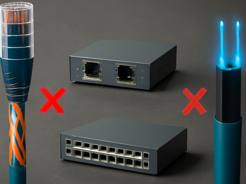
SFP Network Links: Plan a Copper-and-Fiber Connection
SFP modules sit between network equipment and the transmission medium, allowing an Ethernet link to use fiber or copper. A complete SFP network link may run from a switch port to a transceiver, through a patch panel and cable run, to another transceiver, router, or carrier handoff.
The correct design depends on matching each interface to the next one: port and module speed, optical wavelength, fiber type, connector, cable category, termination standard, and segment length. Copper links normally use RJ45 patching and Cat6 or Cat6A cable, while longer or electrically noisy paths generally use fiber.
Map an SFP network link from equipment port to carrier handoff
Identify the port, transceiver, patch point, and cable run
The physical path should be documented as a series of connected segments rather than treated as one interchangeable cable. Each component has a defined position and function:
- Equipment port: A switch, router, firewall, server, or media converter provides an SFP cage, SFP+ cage, RJ45 port, or another network interface. The cage is the receptacle; it is not the transceiver itself.
- SFP module: A pluggable transceiver converts the equipment’s electrical Ethernet signal into an optical or copper interface. An optical module connects to fiber, while a 1000BASE-T SFP provides an RJ45 jack for twisted-pair cable.
- Patch cord: A short, flexible cable connects the module or equipment port to a patch panel, wall outlet, or another active device. Fiber patch cords commonly use LC connectors; copper patch cords use RJ45 plugs.
- Patch panel: A passive termination and organization point presents fixed cabling at a convenient rack or cabinet location. It does not regenerate, convert, or amplify the signal.
- Permanent cable run: This is the structured cabling installed through a building, riser, conduit, or outdoor pathway. It may be copper twisted pair, multimode fiber, or single-mode fiber.
- Remote termination or handoff: The far end may terminate at another patch panel, a switch SFP, a router WAN port, a fiber modem, or a provider-managed optical device.
A simple fiber link therefore follows this order: switch SFP cage → matching SFP module → LC fiber patch cord → fiber patch panel → installed fiber run → remote fiber patch panel → LC patch cord → matching SFP module → receiving switch port. The patch panels are passive; the two SFP modules and the two active equipment ports establish the Ethernet link.
A copper link using an SFP follows a different order: switch SFP cage → RJ45 copper SFP → Cat6 patch cord → copper patch panel → horizontal Cat6 run → wall outlet or remote patch panel → Cat6 patch cord → RJ45 equipment port. The copper SFP must support the speed and cable distance required by that segment.
Complete path: switch port to SFP, patching, run, and handoff
Consider a small office connected to a carrier service and a remote network cabinet. The carrier delivers single-mode fiber to a provider-installed optical network terminal, commonly called a fiber modem. The device converts the provider’s optical service into an Ethernet handoff on an RJ45 port. A short Cat6 patch cord connects that port to the router’s WAN port.
From the router, a 10-gigabit LAN connection uses an SFP+ port loaded with a compatible 10GBASE-SR module. An LC multimode patch cord runs from the module to a rack fiber patch panel. The patch panel connects to an OM4 multimode fiber installed between the main room and a remote cabinet. At the remote cabinet, a second fiber patch panel and LC patch cord connect to a matching 10GBASE-SR module in an access switch.
The access switch then serves local devices through its copper ports. Each port connects with an RJ45 patch cord to a Cat6 patch panel, through a permanent Cat6 cable run to a wall outlet, and finally through another patch cord to a workstation or wireless access point. In this example, the carrier handoff, router WAN, SFP fiber uplink, and local copper access links are separate Ethernet segments with separate compatibility requirements.
That separation matters. A carrier’s optical signal cannot normally be plugged directly into an ordinary switch SFP unless the provider has delivered a compatible Ethernet handoff and the service allows customer-owned optics. The provider device may perform optical-network authentication, wavelength handling, or service conversion before presenting Ethernet to the customer router.
SFP modules and fiber handoffs: match media and speed
Match optical or copper media to the SFP port
An SFP is a form factor, not a guarantee of speed, fiber type, or reach. The module must match both the equipment port and the medium on the other side. Common combinations include:
- 1G SFP with multimode fiber: 1000BASE-SX optics generally use short-wavelength multimode transmission and are intended for building or data-center links over OM-series fiber.
- 1G SFP with single-mode fiber: 1000BASE-LX optics are commonly used on longer building or campus links over OS2 single-mode fiber, although some installations use them over multimode fiber with the appropriate conditioning and distance limits.
- 10G SFP+ with multimode fiber: 10GBASE-SR optics are used with OM3 or OM4 fiber for short-reach 10-gigabit connections.
- 10G SFP+ with single-mode fiber: 10GBASE-LR optics are intended for longer links over OS2 fiber. The permitted reach depends on the optic specification and installation.
- Copper SFP: A 1000BASE-T module provides an RJ45 port and normally uses twisted-pair cable. It is useful when a switch has an SFP slot but the remote connection is a conventional copper Ethernet run.
SFP, SFP+, and SFP28 modules have different speed families. An SFP commonly serves 1 gigabit Ethernet, SFP+ commonly serves 10 gigabits, and SFP28 commonly serves 25 gigabits. A higher-speed cage may support lower-speed modules, but that behavior is equipment-specific. A 10G SFP+ module should not be assumed to operate in a 1G SFP-only port, and a switch may require a particular transceiver type or approved module coding.
Direct-attach copper cables and active optical cables also use pluggable form factors, but they are different from a generic optical SFP connected to a patch panel. A direct-attach cable is normally selected for a short rack or row connection and has a fixed assembly at both ends. It is not a substitute for a structured fiber run.
Check speed, wavelength, connector, and reach
Both ends of a conventional duplex optical link need compatible optics. A 10GBASE-SR module should connect to another 10GBASE-SR module over compatible multimode fiber, while a 10GBASE-LR link normally uses matching single-mode optics. The following details should be checked before installation:
- Speed: Confirm the Ethernet rate supported by the port, module, and remote module. Auto-negotiation behavior also varies between optical standards and equipment.
- Wavelength: Standard duplex optics transmit and receive at defined wavelengths. BiDi or bidirectional optics use different wavelengths in each direction, so the two ends must be purchased as a matched pair.
- Fiber type: Multimode OM1, OM2, OM3, and OM4 are not interchangeable for every optic and distance. Single-mode OS1 and OS2 have different installation characteristics, and the optic’s data sheet determines the supported combination.
- Connector: LC duplex is common for SFP fiber links, but SC, MPO, or other connectors may be used through patching systems. The connector on the patch cord must match the module and panel adapter.
- Reach: A stated maximum distance is meaningful only with the specified fiber, wavelength, loss budget, and connector count. Excessive splices, dirty connectors, or tight bends can reduce the available margin.
- Module support: The switch, router, or firewall may reject an otherwise standard module because of firmware, coding, temperature, or power requirements. The equipment documentation is the final compatibility check.
Transmit and receive paths must also be oriented correctly. A duplex LC patch cord has two fibers: one carries transmit and the other carries receive. If the link remains down after speed and module checks, reversing the two fibers at one end often corrects a transmit-to-transmit or receive-to-receive connection. BiDi links require the correct upstream and downstream optic rather than a simple fiber reversal.
A copper SFP has a separate limit. A 1000BASE-T connection normally supports up to 100 meters for the channel when suitable balanced twisted-pair cabling and patching are used. The module may use more power and generate more heat than an optical SFP, so the switch’s SFP power and thermal specifications should be checked. A copper SFP does not make a 200-meter copper run compliant; it only changes the port interface.
Patch panel, RJ45 wiring, and Cat6 cabling
RJ45 wiring diagram: T568A/T568B pinout and termination
RJ45 is commonly used to describe an eight-contact modular Ethernet plug, although structured-cabling standards technically refer to the 8P8C connector. Ethernet wiring uses four twisted pairs. The most important rule is consistency: terminate both ends of a straight-through cable using T568A at both ends or T568B at both ends.
The pin order below assumes the plug contacts are viewed in the same orientation at each end, with pin 1 identified at the left. The conductor colors are:
- T568A: Pin 1 white/green, pin 2 green, pin 3 white/orange, pin 4 blue, pin 5 white/blue, pin 6 orange, pin 7 white/brown, and pin 8 brown.
- T568B: Pin 1 white/orange, pin 2 orange, pin 3 white/green, pin 4 blue, pin 5 white/blue, pin 6 green, pin 7 white/brown, and pin 8 brown.
T568B is common in many commercial installations, while T568A is also a valid standard. The choice is less important than using the same scheme throughout the permanent link and following the patch panel manufacturer’s color labels. A cable with T568A on one end and T568B on the other is a crossover cable. Modern ports commonly support auto-MDI-X, so crossover wiring is rarely needed for ordinary device connections, but it should not be introduced accidentally.
Ethernet uses pins 1 and 2 as one pair and pins 3 and 6 as another pair for 10BASE-T and 100BASE-TX. Gigabit Ethernet and faster twisted-pair standards use all four pairs, so a cable that appears to work at 100 megabits may still have an open, split, or poorly terminated pair that prevents gigabit operation.
A patch panel does not change the pinout. Its rear IDC terminals follow the selected T568A or T568B color pattern, and its front ports present the same pair arrangement to the patch cord. A termination should preserve each twisted pair as close to the contact as practical. Separating the conductors too far increases crosstalk and can cause a marginal link even when a basic continuity tester reports all eight pins.
Cat6 wiring diagram: terminate and test the run
A Cat6 cable does not require a special pinout compared with other balanced Ethernet cabling. The Cat6 wiring diagram is still T568A or T568B; Cat6 describes the cable’s electrical performance, not a different connector sequence.
For a typical T568B Cat6 installation, the ordered termination process is:
- Plan the permanent link: Route the cable between the patch panel and outlet or remote panel. Keep the total channel within 100 meters, including patch cords.
- Verify the cable type: Use solid-conductor horizontal Cat6 cable for the fixed run and stranded patch cords for equipment connections. Do not use a stranded patch cable as a substitute for a long permanent run.
- Strip only the required jacket: Avoid nicking conductors and keep the twists intact until the cable reaches the termination area.
- Follow the panel or jack label: Select the T568B positions for white/orange, orange, white/green, blue, white/blue, green, white/brown, and brown. Use T568A instead if that is the established site standard.
- Seat the conductors fully: Use the correct punchdown tool on an IDC panel or the specified termination method on a keystone jack. Keep the cable’s pair separator and jacket positioned as the hardware instructions require.
- Install compatible patch cords: Connect the panel to the switch and the outlet to the endpoint with suitable Cat6 cords. Avoid sharp bends, crushing, staples, and excessive tension.
- Test the completed channel: Check wire map, opens, shorts, reversed pairs, split pairs, length, and performance. A qualification or certification tester is more informative than a continuity-only tester for Cat6 performance.
Cat6 performance can be undermined by routing beside high-voltage power, motors, fluorescent lighting, or poorly bonded equipment. Where separation is limited, the installation should follow the applicable cabling and separation requirements rather than relying on shielding alone. Shielded cable also requires compatible shielded connectors, patch panels, and bonding; otherwise the shield does not provide the intended result.
Cat6A versus Cat6: compare 10Gbps distance limits
Both Cat6 and Cat6A can support 1-gigabit Ethernet to a 100-meter channel under compliant installation conditions. The main difference appears when the target is 10-gigabit Ethernet:
- Cat6: 10GBASE-T can operate to approximately 55 meters in many installations, with the actual limit affected by cable construction, neighboring cables, patching, and alien crosstalk. It is suitable for shorter equipment-room, office, and data-center links when the measured channel supports the required rate.
- Cat6A: Designed for 10GBASE-T to 100 meters, including the usual 90-meter permanent link and up to 10 meters of patch cords. It generally provides greater margin against alien crosstalk but is thicker, less flexible, and more demanding in pathways and termination space.
Cat6 is commonly rated to 250 MHz, while Cat6A is commonly rated to 500 MHz. The frequency rating alone does not establish the usable distance; the complete installed channel must meet the relevant performance limits. For a new 10-gigabit link that may approach 100 meters, Cat6A is the safer specification. For a short link or an existing Cat6 installation, certification testing can determine whether Cat6 already meets the intended speed.
The 100-meter figure applies to a complete copper channel, not merely the cable on a reel. A 90-meter permanent link with two 5-meter patch cords uses the full channel allowance. Long patch cords, additional couplers, poorly rated patch panels, or mixed cable categories can reduce the available performance margin.
When an Ethernet extender completes a long copper link
Where a fiber modem fits at the carrier handoff
A fiber modem is commonly the customer-facing name for an optical network terminal, optical network unit, or provider-supplied media device. It sits at the carrier boundary and converts the provider’s optical service into an Ethernet handoff. Depending on the service, its customer port may be RJ45 copper, an SFP slot, or a provider-specific interface.
The usual customer connection is:
Provider fiber → fiber modem or ONT → Ethernet patch cord → router WAN port.
If the device presents RJ45, the router WAN port needs to support the delivered Ethernet speed and the cable should meet the required category. If it presents an SFP handoff, the router must have a compatible SFP cage and module, or a suitable media converter must be placed between the handoff and the router. The module must match the provider’s fiber type, wavelength, connector, and speed; a generic long-reach optic is not automatically suitable for a provider optical network.
A fiber modem is different from an ordinary Ethernet media converter. A media converter typically changes Ethernet from copper to fiber or fiber to copper. A provider optical terminal may also handle the carrier’s passive optical network protocol, service registration, VLAN presentation, or management functions. The carrier normally specifies which interface and patch cable should be used at the handoff.
Choose an extender or fiber conversion by segment length
An Ethernet extender is a pair of active devices that carries Ethernet beyond the normal copper channel limit over an available medium. One unit connects to the local switch or router, the extended medium runs between the units, and the remote unit presents Ethernet to a device or switch.
A copper extension path may look like this:
Switch RJ45 port → short Cat6 patch cord → local Ethernet extender → existing twisted pair, telephone pair, or coaxial run → remote Ethernet extender → short Cat6 patch cord → remote switch or endpoint.
Extenders are useful when a building already has a long copper pair, when installing new fiber is impractical, or when a remote camera, access point, or control device needs a connection beyond 100 meters. They are not passive couplers and normally require power at one or both ends. The achievable speed and distance depend on the extender technology, cable quality, pair count, noise, and manufacturer’s rating.
Before selecting an extender, check:
- Medium: Confirm whether the model uses Cat5e/Cat6 twisted pair, telephone-grade pair, coaxial cable, or another medium.
- Distance and speed: Longer distances usually reduce throughput. Use the product’s distance-versus-speed specification rather than assuming a 100-megapabit or gigabit rate across the entire range.
- Endpoint interface: Verify whether the local and remote Ethernet ports are 10/100, gigabit, SFP, or another interface.
- Power and PoE: Do not assume an extender passes Power over Ethernet. The model must specifically support the required PoE standard, wattage, and voltage budget.
- Duplex and negotiation: Confirm that the extender interoperates with the switch’s auto-negotiation and duplex settings. Some long-reach systems use proprietary modes or require matched units.
- Environment: Outdoor, industrial, or electrically noisy routes may require weatherproofing, surge protection, grounding, or an industrial temperature rating.
For a new connection longer than 100 meters, fiber conversion is usually the more scalable choice. A switch SFP, fiber patch panel, and correctly matched fiber run provide electrical isolation, resistance to electromagnetic interference, and a clearer path to higher speeds. An extender is often the practical choice when the long copper route already exists and replacing it would require major construction.
For short rack connections, a copper patch cord or direct-attach assembly is simpler than either option. For a building-to-building route, a fiber link is generally preferable to extending copper between structures because it avoids ground-potential differences and reduces exposure to induced electrical surges. The final design should therefore identify the longest segment first, then select the SFP, patching, cable category, extender, or carrier handoff that matches that segment’s medium and performance requirement.