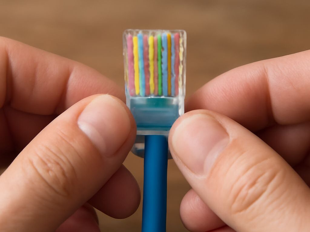
RJ45 Cable Order: T568B Color Code and Connector Pinout
The RJ45 cable order for a T568B Ethernet cable is white/orange, orange, white/green, blue, white/blue, green, white/brown, and brown from pins 1 through 8. For a standard straight-through patch cable, terminate both ends with T568B. The connector must be viewed from the correct side before the colors are arranged.
The T568B pattern applies to both RJ45 plugs and Ethernet jacks, although a jack should be wired according to its printed T568B labels rather than by mirroring a plug visually. The steps below cover the pinout, pair assignments, termination checks, and cable-tester results.
RJ45 Cable Order: Set the Viewing Orientation and Number Pins
To number an RJ45 plug, look directly at the contact end of the clear plug. Hold it with the gold contacts facing toward the viewer, the locking tab underneath, and the cable entering away from the viewer. In this position, pin 1 is on the left and pin 8 is on the right.
Use this orientation when arranging conductors for a plug:
- Pin 1: leftmost contact
- Pin 2: second contact from the left
- Pin 3: third contact
- Pin 4: fourth contact
- Pin 5: fifth contact
- Pin 6: sixth contact
- Pin 7: seventh contact
- Pin 8: rightmost contact
Do not number the plug from the cable-entry side. That reverses the apparent order and can produce a mirrored termination. A wall jack or patch-panel port normally has pin numbers and separate T568A and T568B color markings. Follow the T568B row printed on the jack; the label is the reference for punch-down positions.
RJ45 T568B Color Code: Pins 1–8, Pair Roles, and T568A
The RJ45 T568B color code uses four twisted pairs. The complete connector pinout is:
- Pin 1: white/orange
- Pin 2: orange
- Pin 3: white/green
- Pin 4: blue
- Pin 5: white/blue
- Pin 6: green
- Pin 7: white/brown
- Pin 8: brown
The pin pairs are not arranged as four adjacent pairs. T568B assigns the pairs as follows:
- Orange pair: pins 1 and 2
- Green pair: pins 3 and 6
- Blue pair: pins 4 and 5
- Brown pair: pins 7 and 8
Ethernet signals use pins 1 and 2 with pins 3 and 6 for 10BASE-T and 100BASE-TX. Gigabit Ethernet uses all four pairs, so incorrect pair grouping can cause failures even when a basic continuity tester reports that every conductor reaches the other end.
T568A changes the orange and green pairs but leaves the blue and brown pairs in the same positions:
- Pin 1: white/green
- Pin 2: green
- Pin 3: white/orange
- Pin 4: blue
- Pin 5: white/blue
- Pin 6: orange
- Pin 7: white/brown
- Pin 8: brown
A straight-through cable uses the same standard at both ends: T568B-to-T568B or T568A-to-T568A. A T568A-to-T568B cable is a crossover cable because the orange and green pairs exchange positions. It may still work with modern equipment that supports automatic MDI-X, but it is not the usual straight-through patch-cable arrangement. Mixing standards accidentally is a wiring error when a straight-through cable is required.
RJ45 Connector Pinout: Terminate the Plug or Jack
Before termination, identify the cable category and use a compatible plug or jack. Solid-conductor horizontal cable and stranded patch cable may require different plug designs. The contacts must match the conductor type and cable diameter.
Prepare the cable:
- Remove only enough outer jacket to arrange the conductors and insert them into the plug or jack. Excessive jacket removal leaves the pairs unsupported.
- Separate the four pairs, but preserve their twists as close to the termination point as possible. Keep the untwisted section to about 13 mm, or one-half inch, where the hardware permits.
- Untwist and straighten the conductors only far enough to place them in T568B order. Do not stretch, kink, or sharply flatten the cable.
Terminate an RJ45 plug:
- With the contact end facing the viewer and pin 1 on the left, arrange the conductors in this order: white/orange, orange, white/green, blue, white/blue, green, white/brown, brown.
- Hold the conductors tightly together and trim their ends squarely so they are even.
- Slide the conductor bundle into the plug. Each wire must enter its own channel and reach the front of the plug.
- Check that the outer jacket extends inside the plug far enough for the rear strain-relief tab to grip it. The jacket, not just the individual conductors, should be captured.
- Confirm the order again through the transparent plug. A white-striped conductor that has shifted, crossed, or stopped short is a termination fault.
- Crimp the plug fully with the correct modular-plug tool. The contacts should seat evenly, and the strain relief should hold the jacket without crushing the cable.
After crimping, inspect the plug from both sides. The eight conductors should remain in the correct sequence, all should reach the contact end, and none should be folded underneath another conductor. A contact that has not been driven into its conductor, a conductor that stops short, or a loose jacket indicates that the plug should be cut off and reterminated rather than reused.
Terminate a jack or patch panel:
- Strip the jacket only as far as the hardware instructions require.
- Find the T568B color row on the jack or panel. Do not infer slot positions from the front face of the jack.
- Place each conductor into its labeled IDC slot while keeping the pair twists close to the slots.
- Use a compatible punch-down tool to seat each conductor completely and trim the excess tail.
- Inspect every slot for a conductor that is only partly inserted, a cut or nicked wire, or a conductor placed in the T568A row by mistake.
- Confirm that the cable jacket is held by the jack or panel strain relief. The IDC terminals should not carry the cable’s pulling force.
Do not untwist a pair and then regroup its wires by color family. For example, the white/orange and orange conductors must remain a pair on pins 1 and 2, while the white/green and green conductors must remain a pair on pins 3 and 6. Correct pin numbers with incorrect pair twists can increase crosstalk and prevent the cable from meeting its rated performance.
Read the Cable Tester Result: Opens, Shorts, Reversals, and Split Pairs
Connect the main tester to one end and its remote unit to the other. For a T568B-to-T568B straight-through cable, the expected wire map is:
1-1, 2-2, 3-3, 4-4, 5-5, 6-6, 7-7, 8-8.
The exact display varies by tester, but common results have these meanings:
- Pass or straight-through: Every conductor reaches the matching pin at the far end, and the pair assignments are correct if the tester verifies pairs.
- Open: A conductor does not complete the circuit. Common causes include a wire that did not reach the front of a plug, a contact that failed to pierce the wire, an incompletely punched IDC slot, or a broken conductor.
- Short: Two conductors are electrically connected where they should not be. Look for crossed bare conductors, damaged insulation, a stray strand, or a plug contact that is touching another contact.
- Reversal: The two conductors within a pair are exchanged from end to end, such as pins 1 and 2 appearing in the opposite order. Recheck the orientation before cutting off and replacing the termination.
- Miswire: A conductor reaches the wrong pin because the color order is incorrect or one end was terminated to a different pattern.
- Crossover: One end is T568A and the other is T568B. The tester shows the orange and green pairs exchanged rather than a 1-to-1 map. This is intentional only when a crossover cable is required.
- Split pair: Continuity exists, but conductors from different twisted pairs have been combined. A basic LED tester may show a pass because each pin connects end to end; a wire-map or certification tester that checks pair integrity can identify the split.
When a test fails, compare the tester’s first incorrect pin with the physical termination. Recheck the plug orientation, the full eight-conductor order, pair untwist, conductor seating, jacket capture, and contact or punch-down engagement. If a split pair is suspected, trace the actual twisted pairs through both ends rather than relying only on matching pin numbers.