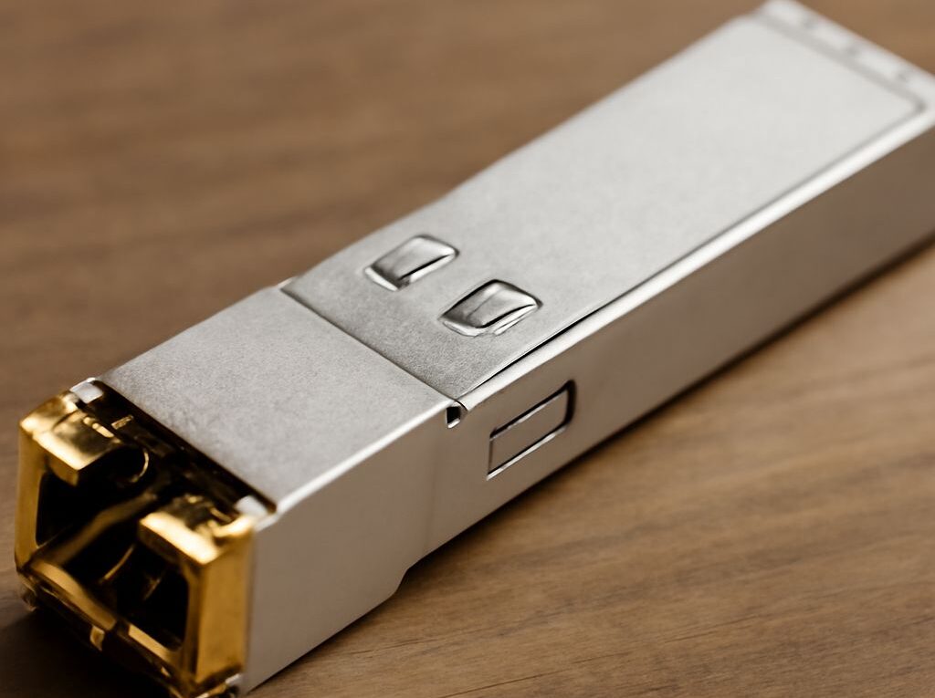
RJ45 Connector Wiring: SFP-to-RJ45 for a 100-Foot Ethernet Cable Run
Correct RJ45 connector wiring, a compatible SFP-to-RJ45 module, and a tested cable are all required for a reliable 100-foot Ethernet link. The 100-foot distance is approximately 30.48 meters, well within the 100-meter channel limit for supported copper Ethernet standards, but the module, cable category, termination, and endpoints must match.
Use the same wiring standard at both ends for a straight-through cable, verify that the host accepts the copper SFP module, and test the completed link for negotiated speed, errors, and temperature.
RJ45 Connector Wiring: T568A/T568B Pin Order and Straight-Through Termination
RJ45 connector wiring uses eight contacts arranged as four twisted pairs. T568A and T568B use the same four pairs but place the orange and green pairs in different positions. Either standard works when used consistently.
- T568A, pins 1 through 8: white/green, green, white/orange, blue, white/blue, orange, white/brown, brown.
- T568B, pins 1 through 8: white/orange, orange, white/green, blue, white/blue, green, white/brown, brown.
For a consistent view, hold the modular plug with the gold contacts facing toward the viewer and the locking tab underneath. Pin 1 is on the left and pin 8 is on the right. Follow the same viewing orientation when arranging the conductors before inserting them into the plug.
A straight-through termination has the same standard on both ends:
- T568A on one end and T568A on the other end; or
- T568B on one end and T568B on the other end.
T568B on one end and T568A on the other creates a crossover cable. Modern Ethernet equipment commonly supports auto-MDI-X, so a crossover may still link, but a straight-through cable is the predictable choice for an SFP-to-RJ45 connection.
- Remove only enough jacket to separate and terminate the pairs.
- Untwist each pair as little as possible. Keep the conductors close to their original twists, especially near the plug.
- Arrange the conductors in the selected T568A or T568B order.
- Trim the ends evenly, push all eight conductors fully into a compatible plug, and crimp with the correct tool.
- Repeat the identical pinout at the far end if a straight-through cable is required.
- Use a wiremap tester to check pin order, opens, shorts, reversed pairs, and split pairs.
The plug must match the cable construction. Solid-conductor installation cable needs plugs rated for solid conductors, while stranded patch cable needs plugs designed for stranded conductors. Category rating, conductor size, shielding, and boot design should also match. A plug can pass a basic continuity test while still producing poor high-frequency performance if the pairs are damaged or excessively untwisted.
SFP-to-RJ45 Module Compatibility: Host Support, Standard, Power, and Heat
An SFP-to-RJ45 module is an active copper Ethernet transceiver. It fits into an SFP or SFP+ cage and presents an RJ45 socket for a twisted-pair cable. It is not a passive adapter, so the host device must recognize and support the module.
Check these specifications before connecting the cable:
- Host support: Confirm that the switch, router, firewall, server adapter, or media converter supports copper RJ45 transceivers in that cage. Some hosts accept only approved vendor modules or require a specific firmware version.
- Form factor: A standard SFP cage generally supports 1Gbps-class SFP modules. An SFP+ cage is designed for higher-speed modules, but compatibility with a particular copper module still depends on the host.
- Ethernet standard: A 1000BASE-T module is intended for Gigabit Ethernet. A 10GBASE-T SFP+ module is intended for 10Gbps Ethernet. Multi-rate modules may support 100Mbps, 1Gbps, 2.5Gbps, 5Gbps, and 10Gbps, but those modes must be supported by both the module and the host port.
- Power budget: Copper modules usually consume more power than short-reach optical modules. The host must provide enough power for the module, particularly when several high-power modules are installed together.
- Thermal limits: 10GBASE-T modules can generate substantial heat because of their signal-processing circuitry. Check the module temperature range, switch airflow, cage restrictions, and host temperature alarms.
- Distance rating: Use the module’s stated maximum distance, not only the cable’s category rating. Some 10GBASE-T SFP+ modules are rated for 30 meters, while others support 100 meters under specified conditions.
A 100-foot run is 30.48 meters before patch cords and equipment connections. A module rated for exactly 30 meters is therefore not an appropriate choice for the full run; select a module rated beyond the complete channel length. For 1Gbps, a 1000BASE-T module commonly supports up to 100 meters over suitable twisted-pair cabling, but the manufacturer’s specification controls.
Vendor coding can also affect link startup. A module may be electrically compatible but rejected by a host that enforces approved transceiver identification. The host documentation should confirm supported part numbers, allowed speed modes, power class, and any port-specific restrictions.
Plan a 100-Foot Ethernet Cable Run: Category, Distance, and Certification
Select the cable category from the required link speed:
- Cat5e or better: Suitable for 1000BASE-T up to the standard channel limit when properly installed.
- Cat6: Provides additional bandwidth and can support 10Gbps over shorter distances, commonly up to 55 meters depending on installation conditions and crosstalk.
- Cat6A: The practical choice for 10Gbps operation across a full 100-meter channel.
For a 100-foot Ethernet cable run, solid Cat6 or Cat6A bulk cable is appropriate for a permanent building route, with short stranded patch cords at the equipment ends. If the cable will be moved frequently, use flexible patch cable and connectors rated for that cable type instead of terminating bulk solid cable with unsuitable plugs.
Keep the route away from power wiring, fluorescent-ballast cabling, motors, and sources of electromagnetic interference. Where a parallel route near power is unavoidable, follow the applicable separation requirements. Do not sharply kink the cable, exceed its bend-radius specification, crush it with staples, or pull it beyond the manufacturer’s tension limit. Avoid tightly bundling large groups of data cables, particularly when using higher-power 10GBASE-T modules.
Shielded cable and shielded connectors are useful only when the complete channel is designed for shielding and the equipment provides the appropriate grounding path. Mixing shielded and unshielded components does not automatically improve performance and can create an inconsistent installation.
Certification is different from a basic wiremap check. A continuity tester can show that every conductor reaches the expected pin, but it cannot prove that the link meets the selected category’s transmission requirements. A cable certifier evaluates the installed link against the applicable performance limit, including measurements such as insertion loss, near-end crosstalk, return loss, propagation delay, and wiremap.
For a permanent installation, test either the permanent link or the complete channel with category-appropriate adapters. Record the result and test both directions as required by the certifier. A failed result should be corrected before the cable is placed in service; common causes include excessive untwist, a split pair, damaged cable, poor plug termination, an incorrect adapter, or a channel that exceeds its length limit.
Test Speed, Temperature, and Stability: Negotiation and Endpoint Checks
After installing the module and cable, verify the link in this order:
- Confirm module detection. Check the host’s interface or transceiver status page for the module identity, supported modes, temperature, and power information. An absent or rejected module must be resolved before troubleshooting the cable.
- Check the physical link. Confirm link indicators at the SFP host and the RJ45 endpoint. If the endpoint is another switch, verify its port status rather than relying only on the LEDs.
- Verify autonegotiation. Leave autonegotiation enabled on both compatible copper Ethernet endpoints unless the equipment documentation specifies another configuration. The two ends must agree on speed and duplex. Forcing one side while leaving the other side to negotiate can create a mismatch or prevent a link.
- Read the negotiated rate. Confirm that the port reports the intended speed, such as 1Gbps or 10Gbps, rather than assuming that a lit LED indicates the target rate. Check the host adapter, switch interface, or operating-system network status.
- Inspect counters. Look for CRC or FCS errors, alignment errors, symbol errors, late collisions, drops, and link flaps. A rising error count under traffic suggests a cabling, termination, interference, module, or port problem.
- Apply sustained traffic. Use an appropriate throughput test between the actual endpoints. A short ping confirms reachability but does not expose marginal pair performance, thermal problems, or reduced throughput.
- Monitor temperature. Check the module and host temperature during sustained traffic. Copper transceivers may become warm during normal operation, but repeated thermal alarms, throttling, unexpected link drops, or a temperature above the manufacturer’s limit indicate inadequate airflow or an unsuitable module.
If the link does not come up, first test with a known-good patch cable and confirm that both ends use the intended pinout. Next verify host approval, module speed support, power budget, and distance rating. If the link negotiates below the expected speed or accumulates errors, retest the permanent channel with a certifier and inspect the terminations for split pairs, excessive untwist, conductor damage, or an RJ45 plug that does not match the cable.