Ethernet Cable Splitter vs. Switch or Fiber: Which Should You Use?
Use an Ethernet cable splitter only when one installed twisted-pair cable must carry two separate 10/100 Mbps links and both ends can use matching adapters. It is a wiring solution, not a device that copies one network connection into two independent full-speed connections.
Use a switch when several devices need normal, independent Ethernet ports, especially at gigabit speeds. Use fiber cables and a 10-gigabit Ethernet switch when the distribution link needs more bandwidth, greater distance, electrical isolation, or an uplink between network closets, floors, or buildings.
What an Ethernet Cable Splitter Actually Does
Passive pair splitting requires two matching adapters
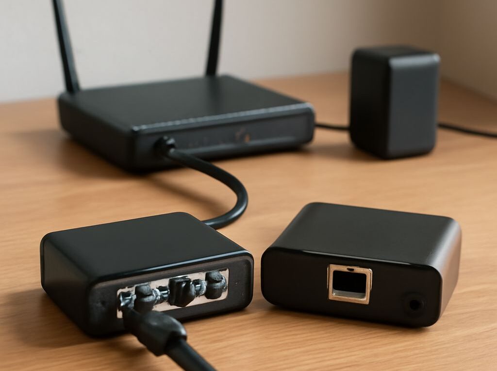
A passive Ethernet splitter separates the four twisted pairs inside a copper cable into two two-pair paths. One pair set connects to one device, while the other pair set connects to a second device. The splitter does not contain a switch, processor, signal regenerator, or address-learning function.
Because the cable is being divided rather than duplicated, a matching adapter is required at both ends of the permanent cable run. A typical installation connects one splitter to two ports on a router or switch, runs one cable through the wall, and connects the second splitter to two devices at the far end. Connecting only one splitter leaves the pin layout unsuitable for ordinary operation.
This arrangement works with Ethernet standards that use two pairs, such as 10BASE-T and 100BASE-TX. It does not provide two gigabit links, because 1000BASE-T uses all four pairs for one link. A passive splitter also cannot turn a single active port into two independently addressed network ports. Each of the two links must originate at its own switch or router port.
Each 100BASE-TX connection can operate at up to 100 Mbps and normally runs in full duplex when connected to a switch. That is two separate 100 Mbps links sharing one physical cable sheath, not two connections sharing one 1 Gbps link. The cable, connectors, patch panels, and network ports must all support the intended wiring arrangement.
Speed, PoE, and power limits
A passive pair splitter normally requires no power because it contains no active electronics. Its main limitation is that it cannot negotiate a faster link than the pairs and attached ports support. If a device expects gigabit Ethernet, a splitter may cause it to fall back to 100 Mbps or fail to establish a link.
Power over Ethernet requires additional care. Standard PoE sends power over the cable pairs according to defined modes, while pair splitting changes how those pairs are allocated. A passive splitter should not be assumed to pass PoE safely or correctly. The switch, splitter, and endpoint must explicitly support the same PoE method. An active PoE splitter, which separates network data from power at the endpoint, is a different product and has its own input, output, wattage, and voltage limits.
A passive splitter is therefore useful for a narrow problem: two nearby, low-bandwidth devices must share one existing cable run, and installing another cable or a small switch is impractical. It is not suitable for expanding a network generally, connecting gigabit endpoints, or powering arbitrary devices.
Why a Switch Creates Independent Ethernet Links
Collision-free links and shared uplink capacity
An Ethernet switch provides a separate physical port and logical forwarding function for each connected device. It learns source MAC addresses, then forwards frames to the appropriate destination port instead of simply repeating every frame everywhere. Modern switched ports normally operate in full duplex, so each link has separate transmit and receive paths and does not use the collisions associated with old shared hubs.
A five- or eight-port gigabit switch is usually the simplest answer when a single network connection must serve several computers, access points, cameras, or other wired devices. Each endpoint can negotiate its own speed, such as 100 Mbps or 1 Gbps, without forcing the others to use a passive pair split.
However, the switch’s connection to the rest of the network remains an uplink. If four devices each send traffic through one 1 Gbps uplink, that uplink can become the bottleneck even though each local port is rated at 1 Gbps. The switch may have sufficient internal switching capacity to forward traffic between local ports, but traffic leaving the switch is limited by the uplink’s negotiated speed.
Power, PoE, and port-count choices
Choose an unmanaged switch for straightforward plug-and-play expansion, or a managed switch when VLANs, monitoring, link aggregation, traffic controls, or centralized configuration are needed. Port speed should match both the endpoints and the upstream connection. A gigabit switch is appropriate for ordinary desktops and many access points; a multigigabit or 10GbE model is more appropriate for servers, storage, video production, or high-capacity uplinks.
Power is another design choice. A standard switch needs local AC power. A PoE switch can supply power to compatible access points, VoIP phones, cameras, and other devices, but its total PoE budget matters. For example, a switch with a 120-watt budget cannot necessarily deliver the maximum rated power to every port at once. Check the device class, per-port limit, cable quality, and total budget rather than treating every PoE port as an unlimited power source.
Unlike a passive splitter, a switch actively receives and retransmits every frame. It can therefore create independent gigabit or faster links, but it also adds equipment, power consumption, heat, and a possible failure point.
Fiber Cables and 10-Gigabit Ethernet Switches for Faster Uplinks
10GbE port types and transceivers
A 10-gigabit Ethernet switch usually provides one or more of three interface categories:
- 10GBASE-T: an RJ45 copper port that commonly supports up to 100 meters over suitable Cat6a cabling. It is convenient when the building already uses copper patch panels and structured cabling.
- SFP+: a modular slot that accepts a compatible 10GbE transceiver, direct-attach copper cable, or optical module. SFP+ is common for switch-to-switch and server connections.
- Other vendor-specific or higher-speed cages: some switches use SFP28 or QSFP interfaces that may support particular lower-speed modules, but compatibility must be confirmed in the switch documentation.
Optical transceivers convert electrical switch signals into light and must match the port, fiber, wavelength, connector, and required distance. A short direct-attach copper cable can connect two SFP+ ports in the same rack without fiber or separate transceivers. It is inexpensive and low-latency, but it is not a substitute for a longer fiber run.
Fiber media, distance, and backplane capacity
Multimode fiber is common for short 10GbE building and data-center links. 10GBASE-SR optics typically support about 300 meters on OM3 fiber and about 400 meters on OM4, subject to the specific optic and installation. Single-mode fiber paired with 10GBASE-LR optics is commonly rated around 10 kilometers, making it appropriate for longer campus or inter-building links when the pathway and optics are designed for that distance.
Fiber cables do not carry electrical power. A fiber-connected access point, camera, or switch therefore needs local power or a copper PoE connection after the fiber terminates at a powered switch. Fiber also does not automatically make every endpoint faster: a 1 Gbps access switch connected by a 10GbE fiber uplink still gives its clients 1 Gbps ports, while the uplink provides more aggregate capacity.
Check the switch’s backplane or switching capacity as well as its port labels. An example switch with twenty-four 1 Gbps ports and two 10 Gbps uplinks has 44 Gbps of nominal one-way port bandwidth. A manufacturer may describe its full-duplex switching capacity as 88 Gbps. That figure indicates the internal forwarding capability under the stated calculation; it does not mean every client can send unlimited traffic through a smaller uplink.
Choose a Distribution Design by Ports, Speed, and Distance
Worked example: a small layout versus a larger one
Small layout: suppose a room has one existing Cat6 cable and needs connections for a desktop, printer, and access point. A five- or eight-port gigabit switch at the room end is the practical choice. It uses one cable as a 1 Gbps uplink and provides independent local ports. If only two 100 Mbps devices are needed and both ends of the cable are accessible, paired passive splitters could use the same run for two 100 Mbps links, but they would not provide a port for a third device or support gigabit operation through the split.
Larger layout: suppose a small office has several 24-port access switches across two floors, file storage, wireless access points, and a server that moves large files. A more suitable design uses a central 10-gigabit Ethernet switch with SFP+ uplinks, fiber cables between the network closets, and copper access ports for ordinary endpoints. Each access switch can use one or two 10GbE uplinks, while local users retain 1 Gbps or multigigabit connections.
For that larger design, use multimode fiber and SR optics when the closets are within the supported building distance. Use single-mode fiber and LR optics for longer inter-building paths. Confirm that every switch has compatible SFP+ support, that the optics operate at the same wavelength and speed, and that the switch has enough backplane capacity for its port mix. If resilience is required, two uplinks can be configured with supported link aggregation or a spanning-tree design rather than simply connecting cables at random.
The decision can be reduced to four checks:
- Need two 10/100 links through one existing cable? Consider paired passive splitters, with no assumption of gigabit speed or automatic PoE support.
- Need three or more devices, independent gigabit links, or flexible expansion? Install a switch with the required port count and an uplink fast enough for expected aggregate traffic.
- Need more than 100 meters, electrical isolation, or an inter-closet connection? Use appropriately matched fiber cables, optics, and switches.
- Need high aggregate throughput? Select a 10GbE or faster uplink and verify transceiver compatibility, PoE requirements, and the switch’s internal switching capacity.