Coaxial to Ethernet Adapter Setup: Carry Ethernet Over Existing Coax
A coaxial to ethernet adapter carries Ethernet frames over an existing 75-ohm coaxial cable by using active electronics at both ends. A typical installation uses one adapter near the router and another near the remote device, with Ethernet patch cables connecting the adapters to RJ45 ports.
The coax connection performs the media conversion; the Ethernet cable connector at each endpoint only terminates the twisted-pair cable. A passive RJ45-to-coax plug cannot translate Ethernet protocol or RF signals. For a reliable installation, select compatible coax adapters, terminate Cat6 with the same wiring standard at both ends, and test the link from the Ethernet port through the complete coax path.
How a coaxial to ethernet adapter converts coax, and why a passive RJ45 plug cannot do it
Ethernet normally travels over four balanced twisted pairs. Coaxial cable uses a central conductor, dielectric, shield, and a different electrical signaling method. An active adapter bridges those media: its Ethernet port receives network frames, converts them to a high-frequency signal for the coax port, and reverses that process at the other adapter.
Common Ethernet-over-coax systems use MoCA or G.hn. Each endpoint needs a powered adapter, although some routers or network devices include built-in MoCA hardware. The usual point-to-point arrangement is:
- Router or switch to an Ethernet port on adapter one.
- Adapter one to the in-wall coax outlet.
- The coax run, couplers, and compatible splitters to the remote outlet.
- Remote coax outlet to adapter two, then adapter two to a computer, access point, television, or switch.
A passive connector changes only the physical termination. It cannot generate the RF carrier, negotiate a coax networking standard, manage multiple nodes, or bridge Ethernet frames. A coax-to-RJ45 plug may therefore look convenient but will not replace a matched pair of active adapters.
Coax adapters also differ from ordinary cable-modem equipment. A cable modem terminates an ISP service, while a MoCA or G.hn adapter creates a local network link over the building’s coax. Some gateways combine both functions, but the coax port and operating mode must still be compatible with the remote adapter.
Choose MoCA or G.hn by endpoint count, shared medium, speed, frequency coexistence, and power
Choose one technology for all adapters on the same coax network unless a manufacturer explicitly supports another arrangement. MoCA is often the straightforward choice in homes that already use cable television or DOCSIS service. G.hn can be useful when a vendor’s kit supports the required coax profile and offers the desired endpoint and management features.
- Endpoint count: A matched MoCA pair supports one remote link, while MoCA networks can generally add multiple adapters within the model’s node limit. G.hn coax systems also commonly support point-to-multipoint operation, but the maximum number of nodes is product-specific. Check whether the stated limit includes the gateway or controller.
- Shared medium: Multiple adapters share the available coax bandwidth. Adding endpoints does not create a dedicated full-speed channel for each device; simultaneous traffic reduces aggregate capacity. A direct, short coax run can perform better than a large splitter tree even when both meet the adapter’s basic requirements.
- Speed: MoCA 2.5 equipment advertises up to 2.5 Gbps of physical-layer capacity, but usable throughput is lower after framing, contention, and cable conditions. G.hn rates vary by profile and vendor, with many coax products advertising roughly 1–2 Gbps. The Ethernet port can also cap the result at 1 Gbps or 2.5 Gbps.
- Frequency coexistence: MoCA commonly operates in high-frequency coax bands and is designed to coexist with supported cable services, but the exact range depends on the device. G.hn frequency profiles also vary. A splitter, amplifier, filter, or television component must pass the adapter’s operating band; a component that passes television channels may still block the data signal.
- Power: Each active adapter needs local AC power unless the specific hardware documents another power method. Coax itself does not power a normal MoCA or G.hn adapter. The remote adapter must remain powered even when its Ethernet device is idle.
For more than two endpoints, use a compatible splitter topology rather than joining coax cables casually. Select splitters rated for the adapter’s full frequency range, commonly including the high band used by MoCA. Avoid cable-amplifier ports that block or regenerate the adapter signal unless the manufacturer confirms compatibility. Unused splitter ports should have proper 75-ohm terminators.
Do not place a MoCA point-of-entry filter between two adapters that need to communicate. If the coax network must be separated from an outside cable plant, install the approved filter at the entry point, before the internal branches. A G.hn system may require a different filter or no filter at all, so its documentation controls the topology.
Select an ethernet cable connector: RJ45 plugs, jacks, and keystones
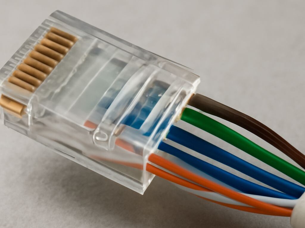
The familiar RJ45 plug is technically an 8P8C modular plug. It is used on patch cords and can be fitted to a Cat6 cable when the plug is rated for that cable’s conductor size and insulation diameter. A wall outlet normally uses a female keystone jack, which connects to a short patch cable. A patch panel uses the same type of punchdown termination in a rack or enclosure.
For permanent in-wall Cat6, a punchdown keystone or patch-panel jack is usually more reliable than crimping a plug onto solid cable. Use stranded, factory-made patch cords for equipment connections. Keep the cable category consistent with the intended link, and use shielded connectors only when the cable, jacks, patch panel, and grounding path are all designed as a shielded system.
When installing an RJ45 plug, remove only enough jacket to arrange the conductors. Preserve the pair twists as close to the contacts as possible, keep the jacket under the plug’s strain relief, and avoid flattening or sharply bending the cable. A connector rated for Cat5e is not automatically suitable for Cat6 cable or its larger conductors.
Use the cat6 pinout (T568A or T568B), orient the plug, and verify link, throughput, isolation, and coax path
The cat6 pinout can use either T568A or T568B. Both carry 100BASE-TX, gigabit Ethernet, and compatible higher-speed signaling when the cable and hardware support it. The important rule is consistency: use the same standard on both ends for a straight-through cable. T568B is common in many new installations, while T568A remains valid and may match existing structured cabling.
To read an RJ45 plug, hold the clear plug with the contacts facing toward the viewer and the locking tab facing away or underneath. Pin 1 is on the left and pin 8 is on the right. The conductor order is:
- T568A: pin 1 white-green, pin 2 green, pin 3 white-orange, pin 4 blue, pin 5 white-blue, pin 6 orange, pin 7 white-brown, pin 8 brown.
- T568B: pin 1 white-orange, pin 2 orange, pin 3 white-green, pin 4 blue, pin 5 white-blue, pin 6 green, pin 7 white-brown, pin 8 brown.
Use the following installation sequence:
- Map the coax: Identify the outlet connected to the router location and the remote outlet. Trace intervening splitters, couplers, wall plates, and amplifiers. Remove unnecessary branches where practical.
- Confirm the adapter pair: Check that both units use MoCA or both use the same G.hn coax profile. Confirm the coax connector type, Ethernet port speed, maximum node count, and supported frequency range.
- Prepare the coax network: Replace incompatible splitters, bypass blocked amplifier ports, and terminate unused ports. Install an approved point-of-entry filter only at the boundary between the internal coax network and outside plant when isolation is required.
- Terminate Cat6: Choose T568A or T568B, arrange all eight conductors in the specified order, keep pair untwist short, seat the jacket under the strain relief, and terminate the other end with the same standard. For a keystone, follow the color labels printed on that jack rather than transferring the plug order directly.
- Power and synchronize: Connect one Ethernet cable from the router or switch to the first adapter and another from the remote adapter to the endpoint. Apply power and wait for the coax or MoCA/G.hn indicators to show synchronization. A power light without a coax light usually indicates a path, compatibility, or frequency problem.
- Check the wire map: Use a cable tester on each Cat6 run. It should report pins 1 through 8 in order with no opens, shorts, reversals, or split pairs. A continuity pass alone is insufficient if the tester does not detect split pairs.
- Check Ethernet negotiation: Read the switch, router, computer, or adapter status page. Confirm that the negotiated rate is appropriate, such as 1 Gbps or 2.5 Gbps, and that the connection is full duplex. A link light proves electrical negotiation, not maximum throughput.
- Measure throughput: Run a wired iperf3 test between two endpoints, or transfer a large file while monitoring the link. Compare the result with the Ethernet port limit and the adapter’s expected usable rate, allowing for protocol overhead and shared traffic.
- Verify isolation and the coax path: Disconnect the remote coax branch and confirm that the corresponding adapter loses its coax link. Check that adapters appear only on the intended internal network, and confirm that an approved entry filter prevents the signal from reaching unrelated outside coax. Reconnect each splitter branch one at a time if the link is intermittent.
If the Cat6 tester fails, correct the termination before troubleshooting the coax. If Cat6 passes but the coax indicator remains off, test the adapters on a short known-good coax cable, then reconnect the installed path. A short-cable success points to a splitter, amplifier, filter placement, damaged cable, or disconnected wall plate in the coax route.