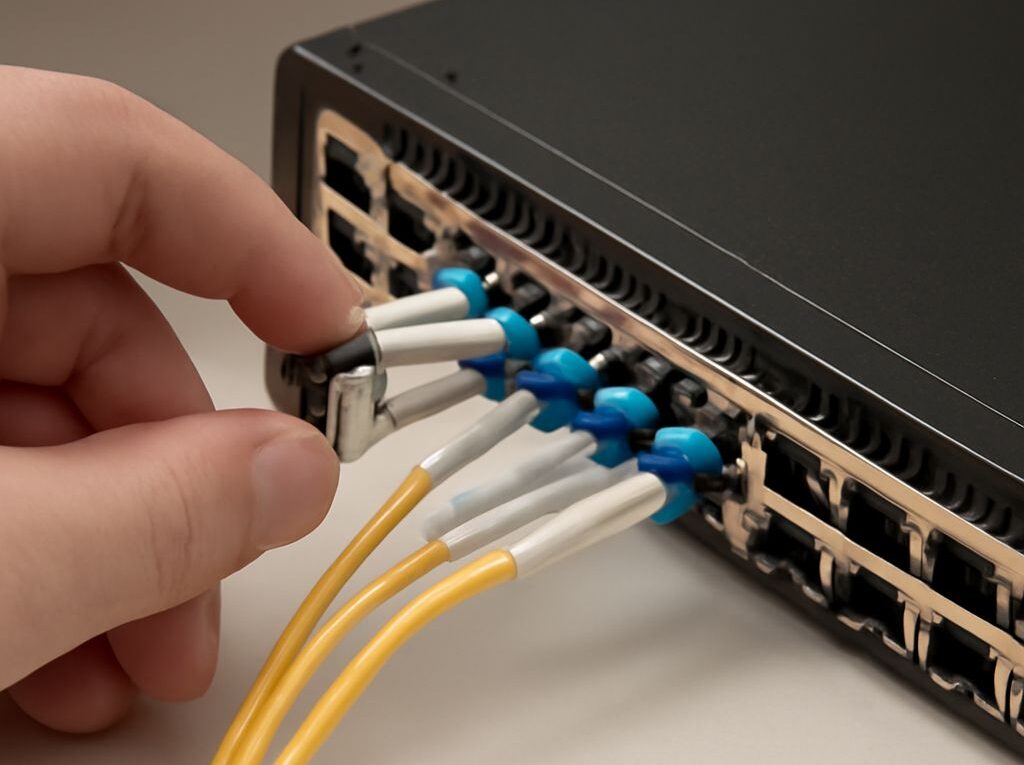
Patch Cable vs Ethernet Cable: Cat6A Cabling and SFP Modules
A patch cable and an Ethernet cable are not opposing categories. A patch cable is a short, flexible cable assembly used to connect equipment, patch panels, and outlets. “Ethernet cable” is a broader term for copper cabling used to carry Ethernet traffic and may refer to either a stranded patch cord or solid horizontal cable.
Cat6A is a performance category for copper cabling, while an SFP module is a pluggable transceiver installed in a network device. Cat6A serves the permanent copper portion of a link; an SFP serves the equipment’s media interface, using either copper or optical media depending on the module.
Patch Cable vs Ethernet Cable: What’s the Difference?
Patch cords: stranded, flexible assemblies for short connections
A patch cord, also called a patch cable, normally uses stranded copper conductors. Each conductor contains multiple fine wires, allowing the cable to bend repeatedly without the rapid fatigue that would affect solid conductors. Patch cords are typically factory-terminated with modular plugs or other connectors and are used where equipment may be moved, replaced, or rearranged.
Common examples include:
- A short cable from a switch port to a patch panel
- A cable from a wall outlet to a computer, access point, or IP phone
- A rack cable connecting a server to a top-of-rack switch
- A pre-terminated cable between equipment and a fiber or copper patch panel
Stranded patch cords are more flexible than solid horizontal cable, but they generally have greater signal loss over the same distance. The cable, plug, and termination should be rated for the intended category. A Cat6A-rated patch cord is appropriate for a Cat6A channel; a lower-category cord can reduce the performance of the complete channel.
Horizontal Ethernet cable: solid conductors for permanent runs
Horizontal cable is the solid-conductor cable installed in walls, ceilings, cable trays, and raised floors. It is designed to be secured in place and terminated at a patch panel, consolidation point, or telecommunications outlet. Solid conductors maintain electrical performance over longer fixed runs, but repeated bending can damage them or change the termination.
For that reason, solid horizontal cable should not normally be used as a convenient replacement for a flexible equipment cord. A solid cable terminated with plugs may work in a limited installation, but it is less suitable for frequent movement and may not meet the relevant channel or connector requirements.
The practical distinction in the patch cable versus Ethernet cable question is therefore the cable’s role and construction:
- Patch cable: usually stranded, flexible, short, and factory-terminated.
- Horizontal cable: usually solid, less flexible, and installed as part of the building cabling.
- Ethernet cable: a general term that can describe either type when it carries Ethernet traffic.
Cat6A Cable in Permanent Links: How the Channel Works
Category ratings and channel requirements
Cat6A cable is a balanced twisted-pair copper medium designed for applications including 10GBASE-T. A compliant Cat6A installation operates to 100 meters when the permanent link, patch cords, connectors, and environmental conditions meet the applicable cabling standard. Cat6A is commonly specified at up to 500 MHz and provides more headroom against crosstalk than Cat6.
The category rating applies to the complete cabling design, not just the printing on one cable jacket. A channel includes the permanent link and the connecting cords at each end. Patch panels, jacks, plugs, consolidation points, and cable construction all affect the result. The lowest-rated or incompatible component can limit the channel.
A typical Cat6A installation uses solid Cat6A horizontal cable between a rack patch panel and a telecommunications outlet, with stranded Cat6A patch cords connecting the patch panel to a switch and the outlet to the endpoint. Cat6A connectors and patch panels should be selected as a matched system, especially where 10 Gb/s operation is required.
Shielded and unshielded Cat6A systems are both available. A shielded design requires compatible shielded components and appropriate bonding and grounding practices throughout the path. Mixing components without checking the manufacturer’s installation requirements can create a channel that is difficult to certify or maintain.
Category and application are related but not identical. Cat6A describes the cabling performance; 10GBASE-T describes an Ethernet signaling application. A Cat6A channel can support lower-speed Ethernet applications, while a lower-category channel may not support every desired speed or distance.
Length accounting from patch panel to device
Length must be calculated across the entire channel rather than from the patch panel to the outlet alone. A commonly used structured-cabling model allows:
- Up to 90 meters for the permanent link, normally the fixed cable between the patch panel and outlet or other fixed termination
- Up to 100 meters for the complete channel, including equipment and work-area patch cords
- About 10 meters combined for patch cords under the usual channel assumptions
The exact allowance depends on the cabling standard, cord construction, temperature, and installation design. Stranded cords may require length derating because their insertion loss is higher than that of solid horizontal cable. High-density racks, long equipment cords, and elevated temperatures can consume the available margin faster than a simple tape measurement suggests.
For example, a 75-meter permanent Cat6A link with 5 meters of patching at one end and 5 meters at the other produces a 85-meter channel. A 90-meter permanent link with 10 meters of patching produces a 100-meter channel only if the components and standard assumptions support that configuration. The permanent-link and channel measurements should be recorded separately during design and certification.
What Is an SFP Module? A Pluggable Transceiver Explained
An SFP is a pluggable transceiver, not a fiber connector
An SFP, or Small Form-factor Pluggable, is a removable transceiver module that fits into a compatible host cage on a switch, router, storage device, media converter, or network interface card. It is not a fiber connector type. The SFP is the electronics and optical or copper interface packaged in a pluggable form factor; the connector on the front of the module is a separate characteristic.
The host device supplies power and presents an electrical network interface to the module. The module then provides the selected physical medium. An optical SFP converts electrical signals into light for transmission over fiber and converts received light back into electrical signals. A copper SFP provides an electrical interface, often through an RJ45 jack, for twisted-pair cabling.
Host cage, module speed, and copper or optical media
The host cage determines which module families and speeds the equipment can support. Standard SFP modules are commonly associated with 1 Gb/s Ethernet, while SFP+ is commonly associated with 10 Gb/s and SFP28 with 25 Gb/s. These labels describe related but different electrical and mechanical capabilities; a port that accepts one form factor is not automatically compatible with every module in the family.
Compatibility must therefore be checked against the device documentation. A switch may accept an SFP+ module in an SFP+ cage and support a lower-speed SFP module, but behavior varies by hardware and software. Some ports support only a specific speed, while others support a defined range. A module that physically fits may still be rejected, operate at the wrong speed, or lack required software support.
Optical modules must also match the fiber medium and reach. Multimode modules commonly use short-wavelength optics such as 850 nanometers, while single-mode designs commonly use wavelengths such as 1310 or 1550 nanometers. These are representative families rather than universal rules; the module specification determines the permitted fiber type, reach, transmit power, and receive sensitivity.
Connector, wavelength, peer matching, and diagnostics
The connector is selected separately from the SFP form factor. An optical SFP may use an LC duplex connector, while a copper SFP may provide an RJ45 port. Some optical modules use a single LC connector for bidirectional transmission, with separate wavelengths traveling in opposite directions. The fiber patch lead must match the module’s connector and polarity requirements.
Both ends of an optical link must be compatible. The peer modules should match on:
- Ethernet speed and supported standard
- Optical medium, such as multimode or single-mode fiber
- Transmission reach and power budget
- Wavelength, including complementary wavelengths for BiDi modules
- Connector type and fiber polarity
- Duplex or bidirectional operating method
- Host-device support, including vendor coding where required
A normal duplex optical link generally uses one transceiver to transmit on one fiber and receive on the other. A BiDi link uses one fiber and requires a complementary pair: one end transmits at one wavelength and receives at the other, while the far end reverses those functions. Two identical BiDi modules are not necessarily a working pair.
Many SFPs support digital optical monitoring, often called DOM or DDM. When both the module and host expose the feature, diagnostics can report values such as module temperature, supply voltage, laser bias current, transmit optical power, and receive optical power. These readings help isolate a dirty connector, excessive loss, failing optic, or unsuitable temperature, but the host must support the monitoring function for those values to be visible.
How to Assemble a Compatible End-to-End Link
Copper path: switch port to Cat6A outlet
A typical copper link begins with a switch’s RJ45 Ethernet port, not an SFP cage. The practical path is:
- Connect a Cat6A stranded patch cord from the switch port to a Cat6A patch-panel port.
- Run solid Cat6A horizontal cable from the patch panel through the building pathway to the telecommunications outlet.
- Connect a second Cat6A patch cord from the outlet to the endpoint.
- Confirm that the permanent-link and total-channel lengths remain within the design limits.
If the switch has an SFP or SFP+ cage instead of a native RJ45 port, a compatible copper SFP can provide an RJ45 interface, subject to the switch’s supported speed and module list. That arrangement still requires the copper channel to meet the selected Ethernet speed. Installing a copper SFP does not turn an overlong or poorly terminated channel into a compliant one.
Optical path: SFP cage to matching SFP and fiber
An optical link uses an SFP-compatible cage at each endpoint, a suitable optical module in each cage, and a fiber assembly between the modules. The assembly process is:
- Verify that each host supports the selected SFP family and operating speed.
- Install modules with matching standard, reach, fiber type, and wavelength requirements.
- Connect the correct fiber connector and polarity at each end.
- Check that the fiber’s length and loss fit within the module’s optical budget.
- Confirm link status and, where available, inspect DOM or DDM readings.
A direct-attach copper cable or active optical cable can also contain pluggable ends for compatible cages. Such assemblies are not interchangeable with ordinary Cat6A patch cords or standard duplex fiber unless the host and cable specifications explicitly support that arrangement.
Final compatibility checks before connecting
- Identify whether each host interface is native RJ45, SFP, SFP+, SFP28, or another module family.
- Match the module’s speed to the port configuration and intended Ethernet application.
- For copper, verify the category of every cord, jack, patch panel, and horizontal cable.
- For optical links, match multimode or single-mode fiber, wavelength, connector, polarity, and reach.
- Account for every cable segment in the channel length, including rack and workstation patching.
- Check module coding, firmware support, temperature range, and diagnostic support when required by the host.
- Inspect and clean optical connectors before insertion, then confirm link negotiation and error counters after activation.