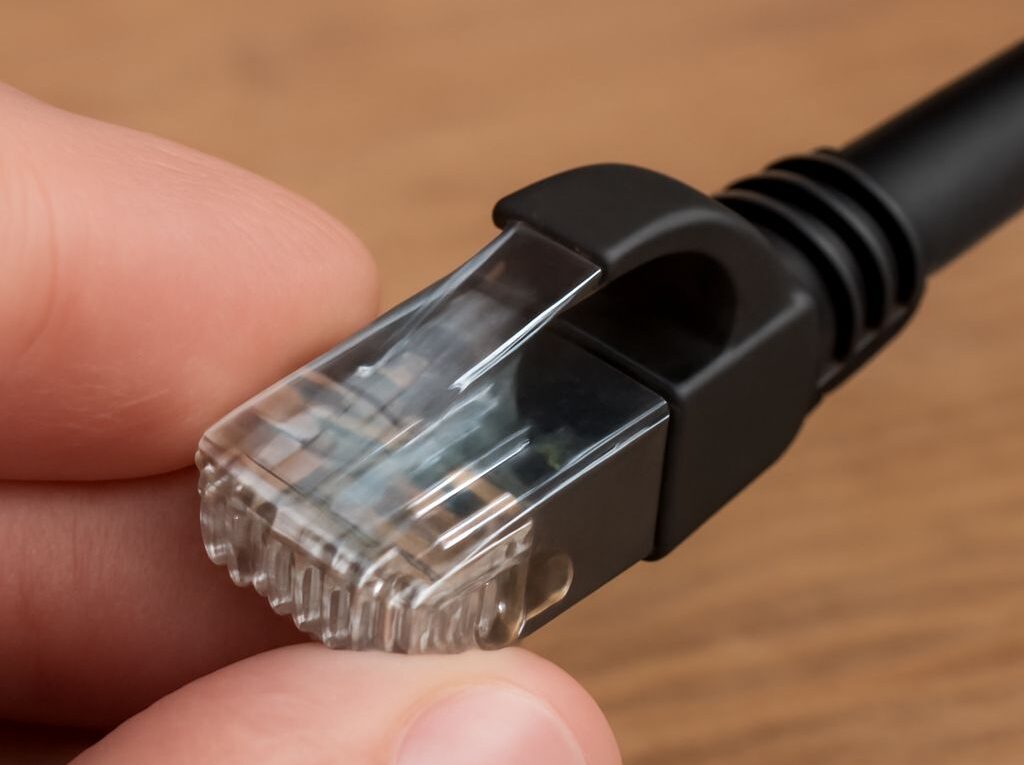
Cat6 speeds: How to make and test an Ethernet cable
Cat6 speeds depend on the Ethernet standard, cable length, installation environment, and termination quality. A correctly installed Cat6 channel can support 1GbE over the full 100 m channel limit. 10GbE is possible over shorter Cat6 runs, while Cat6A is the better choice when 10GbE must reach 100 m.
This guide explains how to choose the cable for the application, prepare and terminate a patch cable with T568A or T568B wiring, and verify both the wire map and the negotiated network speed.
Cat6 speeds: Choose 1GbE or 10GbE by application and distance
Cat6 cable is rated to 250 MHz, but the category rating does not specify one single network speed. The Ethernet standard, channel length, crosstalk, connector quality, and installation conditions determine the usable result.
- 1GbE (1000BASE-T): A normal Cat6 installation supports 1GbE across a compliant 100 m channel, including patch cords.
- 2.5GbE and 5GbE: These multigigabit standards can generally operate over a 100 m Cat6 channel when the cable and installation meet the required specifications.
- 10GbE (10GBASE-T): Cat6 can support 10GbE over shorter channels, commonly up to 55 m. Dense cable bundles, electromagnetic interference, poor connectors, and other sources of alien crosstalk can reduce that distance.
- 10GbE to 100 m: Cat6A is normally selected for a full-distance 10GbE installation because it is designed to manage the additional crosstalk requirements.
For a home office, access point, desktop, camera, or switch connection within a typical room or building, Cat6 is usually sufficient for 1GbE and often suitable for multigigabit networking. For a data-center link, a long backbone, or a planned 10GbE installation, the distance and bundle layout should be checked before choosing Cat6 instead of Cat6A.
Termination quality matters as much as the cable printed on the jacket. Excessive untwisting, a conductor that misses its contact, an incompatible modular plug, or a damaged pair can cause a link to fall back from 1GbE to 100MbE or prevent 10GbE from negotiating at all.
Ethernet cable length: Compare 90 m permanent links with 100 m channels
Ethernet cable length has two commonly confused limits:
- Permanent link: Up to 90 m of fixed horizontal cable, including the connecting hardware at each end. This is the portion normally installed through walls, ceilings, conduit, or cable trays.
- Channel: Up to 100 m from equipment to equipment. The channel includes the 90 m permanent link plus a combined maximum of about 10 m of patch cords and connecting hardware.
A simple example is a 90 m in-wall cable with a 5 m patch cable at each end. Together, those components form a 100 m channel. If the permanent link is shorter, more of the channel allowance can be used for patch cords, but the total channel must remain within the applicable limit.
Do not treat a 100 m channel as 100 m of solid cable plus additional patch leads. Exceeding the channel limit increases attenuation and delay and can make the negotiated speed unreliable. Stranded patch cable also has different electrical characteristics from solid horizontal cable, so long flexible leads should not be used as a substitute for a permanent link.
For 1GbE, staying within the 90 m permanent-link and 100 m channel limits is the main planning rule. For 10GbE on Cat6, use the shorter 55 m maximum as a starting point and reduce it when cables are tightly bundled or the installation has significant interference. A certification tester or the manufacturer’s installation guidance is needed for a precise result in demanding environments.
How to make an Ethernet cable: Tools, plugs, jacket and conductor prep, pair preservation, T568A/T568B order, and crimp checks
Gather the following before starting:
- Cat6 cable of the required length, preferably solid-conductor cable for fixed runs or stranded-conductor cable for a flexible patch lead
- Cat6-compatible 8P8C modular plugs, commonly called RJ45 plugs, matched to the conductor type and outside diameter
- A cable cutter and jacket stripper
- A compatible modular-plug crimp tool
- Optional boots, a cable tester with a remote unit, and a label
Do not mix shielded and unshielded components. A shielded cable requires compatible shielded plugs and grounding practices. Likewise, a plug designed for stranded conductors may not hold solid conductors securely. Check the plug’s conductor-size range before cutting the cable.
1. Cut and strip the cable. Measure the finished length, allowing a small service loop, and cut the cable squarely. Strip only enough outer jacket to arrange the conductors, usually about 30 to 40 mm. Use light pressure with the stripper so the insulation on the individual conductors is not nicked.
Cat6 cable may contain a plastic spline, cross separator, drain wire, or filler. Remove only the parts that prevent the conductors from entering the plug, and cut them back without damaging the conductor insulation. The outer jacket should eventually extend into the plug so the crimp’s strain-relief tab grips the jacket rather than the individual wires.
2. Preserve the twists. Separate the four pairs carefully. Keep each pair twisted as close to the plug contacts as the connector design allows; the T568 termination limit is commonly no more than about 13 mm of untwisted conductor. Excessive untwisting changes the pair’s electrical performance and can create crosstalk, even when a basic continuity tester reports a pass.
3. Select one wiring standard. T568A and T568B are both valid. The important rule for a straight-through cable is to use the same standard at both ends.
- T568A, pin 1 to pin 8: white-green, green, white-orange, blue, white-blue, orange, white-brown, brown
- T568B, pin 1 to pin 8: white-orange, orange, white-green, blue, white-blue, green, white-brown, brown
T568B is common in many existing installations, while T568A is also accepted by structured-cabling standards. Neither provides a higher Cat6 speed. Avoid making an A-to-B crossover cable unless a specific legacy application requires it; modern Ethernet equipment normally handles transmit and receive pairing automatically.
4. Arrange and insert the conductors. Flatten the selected conductors in the required order without rearranging the pairs. With the plug’s gold contacts facing up and the latch underneath, pin 1 is on the left when viewing the contact end. Confirm the plug manufacturer’s orientation if using a pass-through or special connector.
Trim the conductors evenly, then slide them into the plug. Look through the front of the plug to confirm that every conductor reaches the end and remains in the correct channel. The cable jacket must enter far enough for the strain-relief section to grip it. If the jacket stops outside the plug, the conductors can pull out during use.
5. Crimp and inspect the plug. Place the plug fully into the matching crimp-tool cavity and close the tool firmly once. Inspect all eight contacts: each metal pin should be pressed down to a similar depth, and no contact should be lifted, tilted, or backed out. Check the front for the correct color order and verify that no conductor is short, twisted out of its channel, or missing from the end.
Inspect the rear of the plug as well. The jacket should be held by the strain relief, with no excessive bare conductor between the jacket and the contacts. Replace the plug rather than trying to repair a questionable crimp. Repeat the same process at the other end using the same wiring standard.
Test the wire map: Interpret passes, opens, shorts, split pairs, and negotiated link speed
Start with a wire-map test before connecting the cable to network equipment. Plug one end into the tester’s main unit and the other into its remote unit. A correctly wired straight-through cable should report:
- Pin 1 to pin 1
- Pin 2 to pin 2
- Pin 3 to pin 3
- Pin 4 to pin 4
- Pin 5 to pin 5
- Pin 6 to pin 6
- Pin 7 to pin 7
- Pin 8 to pin 8
A tester may display the result as a sequence such as 1-2-3-4-5-6-7-8 or as eight matching LEDs. The exact display varies, so the tester’s legend takes priority.
- Pass: All eight conductors have continuity and the pin order is correct. On a basic tester, this does not prove that the cable meets every high-frequency Cat6 performance requirement.
- Open: A conductor is not connected end to end. Common causes include a conductor that did not reach the plug contacts, a pin that was not crimped, or a broken wire near the plug.
- Short: Two conductors are electrically connected when they should not be. Look for damaged insulation, crossed contacts, a bent pin, or stray copper inside the plug.
- Miswire or reversed pair: Continuity exists, but a conductor reaches the wrong pin or the two wires within a pair are reversed. Re-terminate the affected end.
- Split pair: The tester sees continuity on all eight pins but the conductors are paired incorrectly. This can pass a simple pin-by-pin test while causing severe crosstalk and poor performance. A pair-aware tester or certification tester is required to identify it reliably.
After the wire map passes, connect the cable between a switch, router, computer, access point, or other Ethernet devices. Check the network adapter or switch status for the negotiated link speed. A reading of 1.0 Gbps full duplex confirms a gigabit link under those port and cable conditions. A 10 Gbps reading confirms that the endpoints negotiated 10GbE, but it does not by itself prove that every possible length or installation condition will support that speed.
If the link negotiates at 100 Mbps, 10 Mbps, or repeatedly disconnects, check the plugs, pair order, cable length, port settings, and the two network ports. Test with known-good equipment to separate a cable fault from a device fault. A wire-map pass followed by a low-speed link often points to excessive untwist, a split pair, damaged cable, unsuitable plugs, or a run that is too long for the intended speed.
For critical or long installations, use a certification tester rather than a basic continuity tester. It can measure length, insertion loss, return loss, and crosstalk and can determine whether the permanent link or channel meets the required Cat6 performance class.