LC Fiber, 1000BASE-T, and 10GbE Switch Interfaces
LC fiber, 1000BASE-T, and a 10Gb network switch describe different parts of a link. LC identifies the connector format; 1000BASE-T identifies 1Gbps Ethernet over twisted-pair copper; and a 10GbE switch may use RJ45 ports, SFP+ cages, copper modules, optical transceivers, DAC cables, or AOCs.
Before connecting a port, match the Ethernet standard, media, module, connector, fiber mode, wavelength, distance, and peer capability. A connector that fits mechanically does not guarantee that the link will operate.
LC fiber: connector, fiber mode, wavelength, and reach
LC is a small fiber-optic connector, not an Ethernet speed or fiber type. An LC duplex connector normally carries two fibers: one for transmit and one for receive. LC cables can use either multimode fiber (MMF) or single-mode fiber (SMF), and the connector alone does not identify which mode is present.
The optic installed at each end determines the Ethernet speed, wavelength, and supported reach. Common examples include:
- 1000BASE-SX: 1Gbps over multimode fiber, typically using an 850nm wavelength. Reach depends on the fiber grade, with common limits ranging from about 220 meters on older fiber to 550 meters on suitable OM2, OM3, or OM4 fiber.
- 1000BASE-LX: 1Gbps, normally using a 1310nm wavelength and single-mode fiber for reaches up to about 5 kilometers. Some installations use it over multimode fiber with the appropriate conditions or mode-conditioning cable.
- 10GBASE-SR: 10Gbps over multimode fiber at approximately 850nm. Reach is commonly 300 meters on OM3 and 400 meters on OM4, subject to the optic and cabling specifications.
- 10GBASE-LR: 10Gbps over single-mode fiber at approximately 1310nm, commonly reaching up to 10 kilometers.
Optical links usually require a compatible transceiver at each end. A 10GBASE-SR optic must connect to a peer that supports the same 10GbE optical standard and a compatible multimode path. A 10GBASE-LR optic requires a suitable single-mode path. Connecting an SR optic to an LR optic, or multimode fiber to a single-mode optic, is not a valid general-purpose pairing even if both connectors are LC.
Check polarity as well as connector type. A duplex LC patch lead must route the transmit fiber from one side to the receive fiber on the other. A polarity reversal can produce no link even when the optics and fiber mode are correct. BiDi optics are a special case: they use one fiber and matched transceivers with different transmit and receive wavelengths. They must be installed as a compatible pair rather than mixed with ordinary duplex optics.
Fiber Ethernet is full duplex. Unlike copper, it does not use cable pairs for automatic speed and duplex selection in the usual way. Many optical ports operate at a fixed line rate determined by the installed module. Clean connectors, correct fiber mode, matching wavelengths, and an optic supported by the switch are more important than simply selecting an LC cable.
1000BASE-T over twisted-pair copper: speed, category, and negotiation
1000BASE-T is 1Gbps Ethernet over balanced copper twisted pair. It uses all four pairs in the cable and normally operates as a full-duplex link. The standard supports a maximum channel length of 100 meters, including the horizontal cable, patch panels, and patch cords.
Cat5e is the usual minimum category for a compliant 1000BASE-T installation. Cat6 and Cat6A also support 1000BASE-T and can provide additional noise margin or support higher-speed standards over the same pathway. A cable labeled Cat6A does not make a 1000BASE-T port faster; the port and its peer still determine the negotiated speed.
The physical connector is normally an 8P8C modular plug commonly called RJ45. This is different from LC fiber. An RJ45 copper port cannot accept an LC patch lead, and an LC SFP transceiver cannot be substituted for an RJ45 port without a suitable switch cage and module.
1000BASE-T normally uses Ethernet auto-negotiation to agree on speed and duplex with the peer. Both ends should generally be left on auto-negotiation. A forced setting at one end can prevent a link or cause a mismatch, especially if the other end is negotiating. A gigabit link that reports 100Mbps often indicates a damaged pair, an incorrectly terminated cable, or a device that cannot support 1000BASE-T. Because gigabit operation uses all four pairs, a two-pair cable fault can reduce the link to a lower mode or prevent link establishment.
For a copper access connection, a workstation with a 1Gbps network adapter can connect to a switch 1000BASE-T port through Cat5e or better cabling up to 100 meters. For a 10GbE connection over copper, the requirements change: 10GBASE-T commonly needs Cat6A for a 100-meter channel, while Cat6 reach can be limited by the installation and noise environment, often to approximately 55 meters. The switch, transceiver, network adapter, and cable must all support 10GBASE-T.
10GbE switch port types, modules, connectors, and transceivers
A 10GbE switch does not have one universal physical interface. Read the port label and the switch specifications before choosing the cable or module.
- 10GBASE-T RJ45 ports use twisted-pair copper. With suitable Cat6A cabling, the normal maximum channel is 100 meters. These ports commonly support auto-negotiation and may also accept lower speeds such as 5Gbps, 2.5Gbps, or 1Gbps, but the supported rates vary by model.
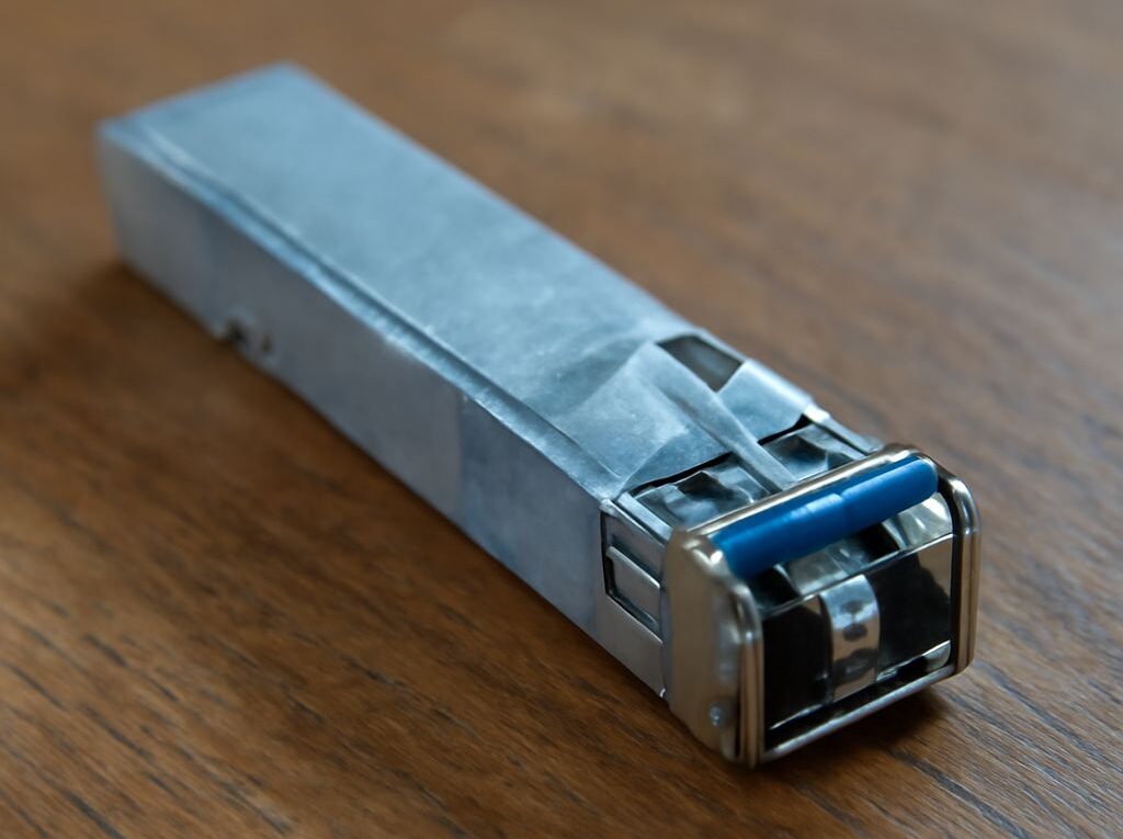
- SFP+ cages accept compatible 10GbE transceivers, direct-attach copper (DAC) cables, or active optical cables (AOCs). An SFP+ cage is a module slot, not an LC connector by itself. The installed transceiver determines whether the link uses LC fiber, another optical format, or a short copper assembly.
- 10GBASE-SR SFP+ optics use duplex LC connectors and multimode fiber, usually at 850nm. They suit short building, server-room, and data-center links.
- 10GBASE-LR SFP+ optics normally use duplex LC connectors and single-mode fiber at 1310nm for links up to about 10 kilometers.
- SFP+ DAC cables use integrated copper assemblies for short switch-to-server or switch-to-switch links. They do not use LC connectors, and their supported length and coding are specific to the cable and switch vendors.
- AOCs combine optical cable and fixed transceiver ends. They can cover longer rack or row connections than DAC cables without requiring separate SFP+ optics, but support and length remain vendor-dependent.
Transceiver support is a key selection requirement. Some switches accept only vendor-coded modules; others accept a wider range of standards-compliant optics. Some SFP+ ports support both 1Gbps and 10Gbps modules, while others support 10Gbps only. A switch may also restrict which ports can operate at a lower speed or may require a configuration change.
Auto-negotiation differs by interface. 10GBASE-T normally negotiates with its copper peer. Standard 10GbE optical connections and DAC links are commonly treated as fixed-speed links, so both ends must use compatible 10Gbps interfaces. A 10Gbps SFP+ port with a 1Gbps SFP optic works only when the switch and the peer explicitly support that mode.
For example, an access switch can connect 1Gbps user devices through 1000BASE-T RJ45 ports, then use two 10GBASE-SR SFP+ uplinks over OM4 multimode fiber to a core switch in the same building. If the uplink must travel several kilometers between buildings, paired 10GBASE-LR optics and OS2 single-mode fiber are a more suitable choice. For servers in the same rack, a supported 10GbE DAC may be simpler than separate optics and LC patch leads.
Match both ends, then verify link state, diagnostics, and throughput
Use the following sequence to prevent a connector or module mismatch from becoming a troubleshooting exercise:
- Identify both ports. Record the Ethernet standard, rated speed, port type, supported modules, and expected peer. Confirm whether each side is 1000BASE-T, 10GBASE-T, SFP+, or another interface.
- Match the media. For copper, verify Cat5e or better for 1000BASE-T and the appropriate category and distance for 10GBASE-T. For fiber, verify MMF or SMF, optic standard, wavelength, connector, polarity, and the channel length.
- Confirm transceiver support. Check that the switch recognizes the module or cable and that both ends support the selected speed. Do not assume that an SFP+ cage supports every SFP or SFP+ optic.
- Inspect and seat the connection. Fully insert RJ45 plugs and modules. Inspect fiber end faces, clean them with suitable fiber-cleaning equipment, and check duplex polarity. Avoid looking into an active fiber port.
- Read link state and negotiated properties. The switch and endpoint should show link up at the expected speed and full duplex. For copper, check auto-negotiation results. For optical ports, check the configured speed and module identity. A link that comes up at an unexpected rate indicates a capability, configuration, or physical-layer issue.
- Review diagnostics and counters. Examine CRC or FCS errors, symbol errors, runts, discards, link flaps, and interface resets. Where supported, digital optical monitoring can show module temperature, voltage, transmit power, and receive power. Low receive power, rising errors, or unstable readings can indicate dirty connectors, excessive loss, wrong polarity, or a damaged fiber path.
- Test throughput in both directions. Use a suitable tool such as iperf3 with capable endpoints and a controlled path. A healthy single 1Gbps TCP path commonly measures around 900 to 950Mbps, while a 10Gbps path may approach 9 to 9.5Gbps under favorable conditions. Results below line rate can reflect host CPU, storage, TCP window, adapter settings, congestion, or packet errors rather than an interface mismatch.
If there is no link, check the standard and module pairing first, then polarity, fiber mode, wavelength, cable pairs, and port configuration. If the link is up but throughput is poor, use interface counters and optical or copper diagnostics before replacing hardware.