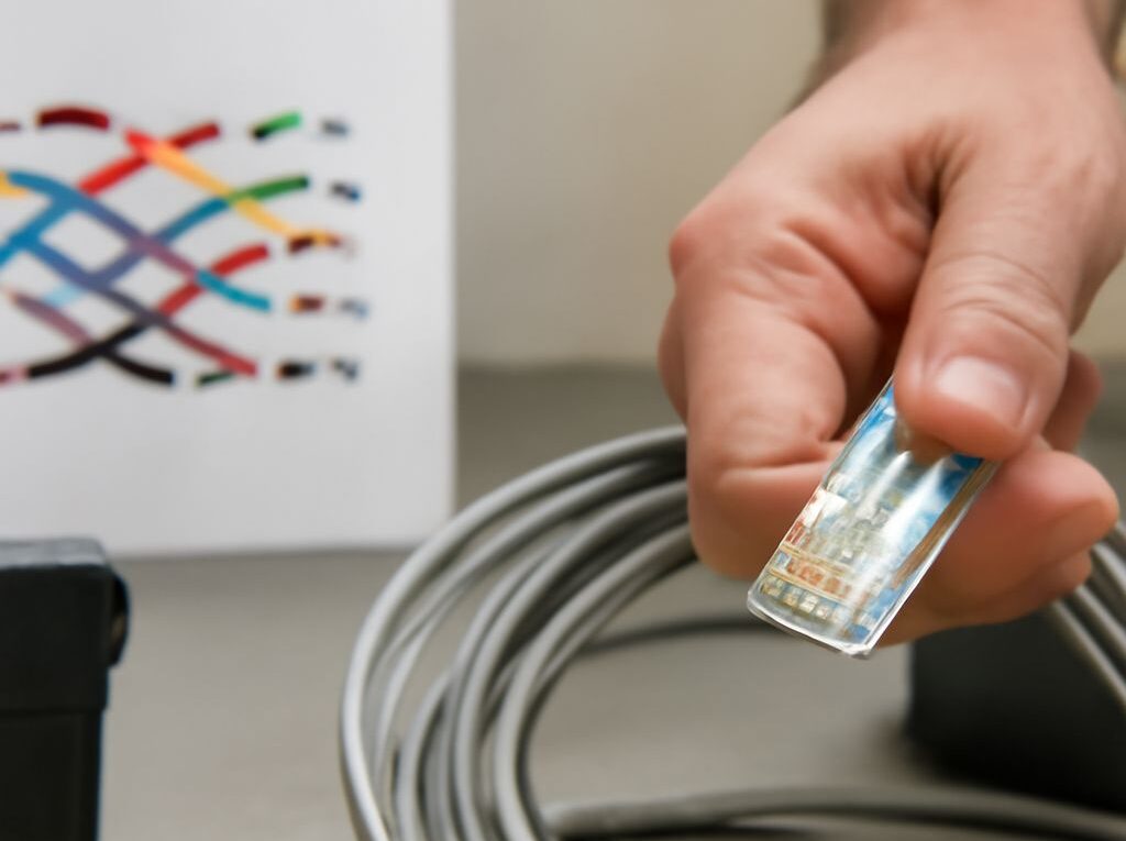
Best Ethernet Splitter: When You Need a Switch and How to Wire Ethernet
For most homes and small offices, the best Ethernet splitter setup is actually a small unmanaged gigabit switch. A switch connects to one router or network outlet and provides separate ports for multiple devices. It supports independent links, normal auto-negotiation, and gigabit speeds when the cable and hardware support them.
A passive Ethernet splitter is different. It does not contain switching electronics and cannot turn one network port into two independent full-speed ports. It only rearranges the four twisted pairs in a cable, so its use is limited to specific 10/100 Mbps installations. Cable category also matters: Cat5e is usually enough for gigabit Ethernet, while Cat6A is the practical choice for 10Gbps over longer runs.
Best Ethernet Splitter Setup: Why a Switch Is Usually Better
Passive pair splitting and the paired-adapter requirement
A standard Ethernet cable contains four twisted pairs, or eight conductors. 10BASE-T and 100BASE-TX use two pairs: pins 1–2 and 3–6. Gigabit Ethernet and faster standards use all four pairs.
A passive splitter assigns the first 10/100 link to pins 1, 2, 3, and 6, then assigns a second 10/100 link to pins 4, 5, 7, and 8. There are no active components to regenerate signals, negotiate speeds, route traffic, or provide power.
Two matching adapters are required. A typical arrangement is:
Two switch or router ports → splitter → one four-pair cable → splitter → two devices.
The splitter at each end recombines the correct pairs for the two separate connections. Using one passive splitter by itself does not split a normal network port into two usable ports. The upstream side must provide two physical Ethernet ports, and the remote side must connect to two devices.
Port independence, speed limits, and the case for a switch
Each passive-splitter connection is limited to 10 or 100 Mbps because gigabit Ethernet requires all eight conductors. The splitter itself does not provide port independence; it only lets two existing 10/100 links share one cable route. Both links also depend on correctly wired adapters at both ends.
A switch is the normal solution when more devices must connect at one location. A five- or eight-port unmanaged gigabit switch usually needs only one cable to the router or wall outlet, leaving the other ports available for computers, televisions, access points, cameras, or game consoles. Each port can negotiate its own speed and operate independently. A switch is preferable when:
- Devices need gigabit or faster speeds.
- Only one network cable is available but there is power for a switch.
- More than two remote devices may be added later.
- The installation should support normal link negotiation and easier troubleshooting.
A passive splitter remains useful when a second cable cannot be installed, both links only need 100 Mbps, and the installation already has two network ports at the source. It is not a replacement for a switch.
Cat5 vs Cat6 vs Cat7: Which Cable Category Fits Your Network?
Cat5 and Cat5e: legacy cabling versus everyday Ethernet
Cat5 is an older 100 MHz category generally associated with 10Mbps and 100Mbps Ethernet. A properly installed Cat5 run may support gigabit Ethernet in some circumstances, but it is not the preferred choice for new work.
Cat5e is the enhanced version and the usual minimum for new gigabit cabling. It is rated to 100 MHz and supports 1000BASE-T up to 100 meters when the complete channel, including connectors and patch leads, is installed correctly. Cat5e is suitable for most home networks, internet connections, printers, streaming devices, and ordinary office links.
Cat6 and Cat6A: the practical upgrade path
Cat6 is rated to 250 MHz and supports gigabit Ethernet to 100 meters. It can support 10GBASE-T over shorter distances, commonly up to about 55 meters depending on cable construction, installation quality, and crosstalk conditions. Cat6 is thicker and usually less flexible than Cat5e, but it offers a useful margin for new in-wall installations.
Cat6A is rated to 500 MHz and is designed to carry 10GBASE-T to 100 meters. It is the better choice for long 10Gbps runs, server rooms, high-performance workstations, and installations intended to remain useful for many years. Cat6A is generally larger, stiffer, and more difficult to route than Cat6, so the higher category is not automatically better for a short patch cable.
For most new residential wiring, Cat6 provides the best balance of cost, flexibility, and future capacity. Cat5e is adequate where gigabit is the target and the route is straightforward. Choose Cat6A when 10Gbps at the full 100-meter channel length is a defined requirement.
Cat7: shielding, labels, and connector compatibility
Cat7 is an ISO/IEC Class F cable designation commonly associated with 600 MHz operation and extensive shielding. It can support 10Gbps to 100 meters in a suitable channel, but a Cat7 label does not make a network device faster than its ports or make a poor termination perform better.
True Class F systems may use specialized GG45 or TERA connectors. Many retail products marketed as Cat7 use shielded, RJ45-compatible connectors instead. Before buying, confirm that the cable, plugs, jacks, and patch panel use compatible connector types and shielding. Shielded components also need appropriate shield continuity and grounding practices.
For ordinary RJ45 networks, Cat7 is rarely necessary. A correctly installed Cat6 or Cat6A system is normally simpler and more compatible. Category ratings describe the cable and channel performance; they do not override the speed limits of switches, network adapters, or routers.
Cat6 Wire Order: T568A vs T568B Pinouts
The Cat6 wire order is the same basic eight-position arrangement used for other balanced Ethernet categories. T568A and T568B have identical electrical performance when both ends use the same standard. They differ only in which color pair occupies the orange and green positions.
T568A color order for conductor positions 1–8
View an RJ45-style plug with the gold contacts facing up, the cable entering from the rear, and position 1 on the left. The T568A sequence is:
- White with green stripe
- Green
- White with orange stripe
- Blue
- White with blue stripe
- Orange
- White with brown stripe
- Brown
T568B color order for conductor positions 1–8
Using the same viewing orientation, the T568B sequence is:
- White with orange stripe
- Orange
- White with green stripe
- Blue
- White with blue stripe
- Green
- White with brown stripe
- Brown
Choosing one wiring standard for both ends
Use the same standard on both ends for a straight-through patch or permanent link. T568B is common in many installations, while T568A is used where a project specification or existing building wiring requires it. Neither is inherently faster.
Do not choose the standard based only on the order of colors printed on a plug. Keystone jacks and patch panels usually show separate A and B labels; follow the selected label for every conductor. Mixing A on one end and B on the other creates a crossover cable. Modern equipment often corrects this with auto MDI-X, but a consistent standard is easier to document and troubleshoot.
Build, Terminate, and Test the Ethernet Connection
Termination steps, tools, and connector choice
- Select the cable type. Use solid-conductor Cat5e, Cat6, or Cat6A cable for fixed in-wall runs. Use stranded patch cable for short, flexible connections. Select plugs and jacks rated for the cable category and compatible with the conductor type.
- Plan the route. Avoid excessive pulling force, sharp bends, crushing, and long parallel runs beside power wiring. Follow the cable maker’s minimum bend radius, especially with thicker Cat6A or shielded cable.
- Strip the jacket carefully. Remove only enough jacket to reach the connector or punchdown. Do not nick the insulation or copper conductors. Remove a central spline or separator only if the connector instructions require it.
- Choose T568A or T568B. Use the same selected standard at both ends. Keep each twisted pair together and preserve the twists as close to the termination point as practical; about 13 millimeters or less of untwisted conductor is a useful maximum for typical terminations.
- Terminate the ends. For a modular plug, place the conductors in positions 1–8, trim them evenly, slide them fully into the plug, and crimp with the correct tool. For a keystone jack or patch panel, seat each conductor in the matching color slot and use a punchdown tool.
- Inspect the work. Confirm that the jacket is held by the strain relief, no conductor is short of its contact, the pairs are not rearranged, and any shield is continuous through compatible shielded hardware.
Factory-made patch cables are often more reliable than hand-crimped plugs. For permanent cable, a keystone jack or patch panel with a short factory-made patch lead is usually easier to terminate and replace than a plug fitted directly to solid horizontal cable.
Wire-map testing for continuity, pair order, and faults
Test the cable before relying on the network connection. Place the main unit of an Ethernet cable tester at one end and its remote unit at the other. A correct straight-through T568A or T568B cable should show positions 1 through 8 in the same order at both ends.
The tester should identify:
- Open conductors, where a pin has no continuity.
- Shorts between conductors.
- Reversed conductors or reversed pairs.
- Misplaced conductors caused by using the wrong color sequence.
- Split pairs, where continuity exists but the two conductors no longer form the correct twisted pair.
A basic continuity tester may not detect every performance problem, so confirm the finished link by connecting it to a switch and checking the negotiated speed. A gigabit-capable connection should normally negotiate at 1Gbps when both devices and the cable support it. If it falls back to 100Mbps, inspect the terminations, check for a split pair, and confirm that all eight conductors are present. Throughput testing can then distinguish a cabling fault from a limitation in the network hardware or service.