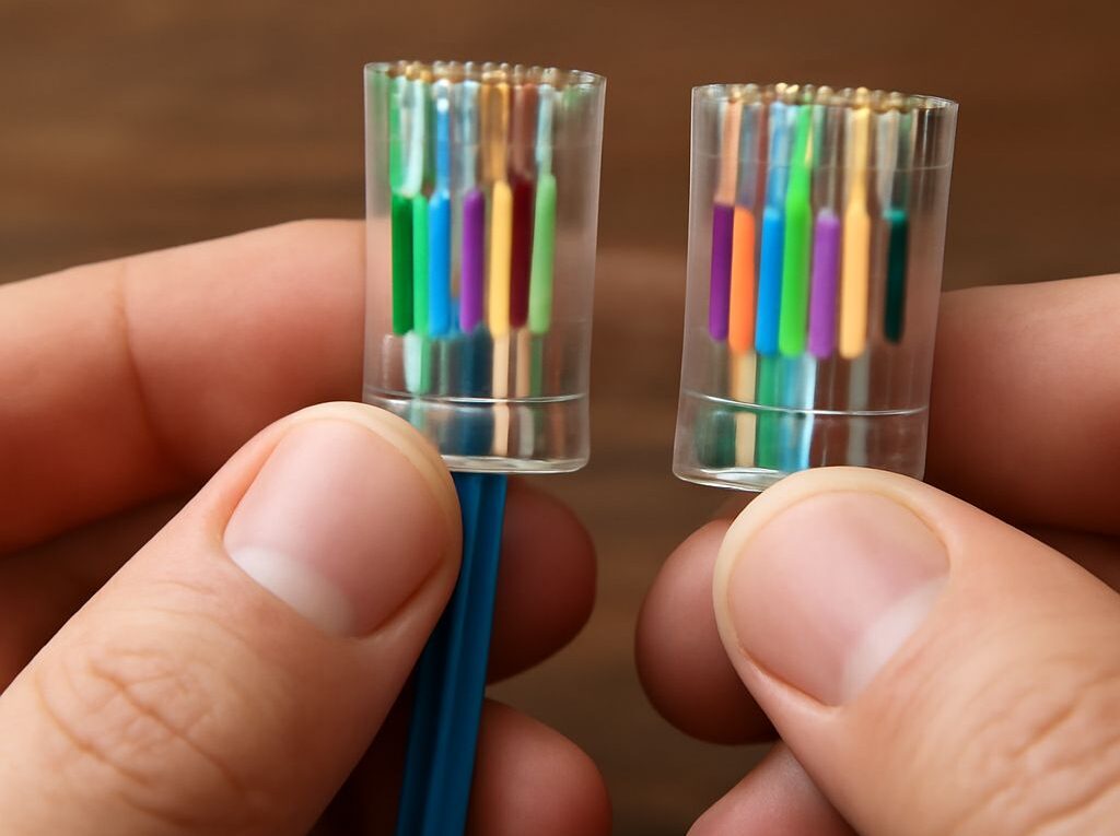
RJ-45 Pinout: T568B Color Code and Wiring Guide
The RJ-45 pinout is the ordered arrangement of eight conductors inside an Ethernet plug. For the T568B wiring scheme, pin 1 starts with white/orange and pin 8 ends with brown when the plug is viewed with its contacts facing forward and its latch down.
The RJ45 cable color code below gives the complete T568B sequence, pair assignments, and a practical termination check. Correct color order is necessary, but a cable can still fail because of excessive untwist, poor conductor seating, an exposed jacket, or a split pair.
RJ45 pinout: orient the plug before numbering pins
Looking into the plug: contacts toward you, latch down
Pin numbers depend on the viewing direction. Hold the clear modular plug so the eight gold contacts face the viewer, the locking latch points down, and the cable enters from the rear. In this position, count from left to right: pin 1 is on the left and pin 8 is on the right.
This front-facing view is the standard reference for the T568B color list. The conductors are inserted into the plug from the rear, but their contact positions are read from the front. The cable jacket and conductors should not be used to identify pin 1; the plug orientation must be established first.
- Contacts facing the viewer, latch down: pin 1 is left and pin 8 is right.
- Contacts facing the viewer, latch up: the visible order is reversed, so pin 1 is right and pin 8 is left.
- Plug viewed from the cable-entry side: do not copy the front-view order without reversing the perspective.
A common mistake is to look at the plug with the latch facing the viewer and then count the contacts from the same side used for the front view. That reverses the sequence and can produce a cable that looks orderly but fails its wire-map test.
Looking into a jack: use the socket’s pin-1 position
An RJ45 jack is not numbered by assuming that its leftmost visible contact matches the plug’s pin 1. Keystone jacks, patch panels, and wall outlets usually identify positions with printed numbers, a T568A/T568B label, or a color diagram. Use that marking when terminating the jack.
When inspecting a socket from the front, locate the molded or printed pin-1 mark and follow the jack’s labeled sequence. The jack may present the contacts in a different physical orientation from a plug because its contacts are mounted inside a keyed housing. A T568B plug can therefore be read with the plug diagram, while a T568B jack should be terminated from the jack’s own pin labels.
RJ45 cable color code: the T568B pinout for pins 1–8
Pins 1–8: white/orange, orange, white/green, blue, white/blue, green, white/brown, brown
The T568B sequence is:
- Pin 1: white/orange
- Pin 2: orange
- Pin 3: white/green
- Pin 4: blue
- Pin 5: white/blue
- Pin 6: green
- Pin 7: white/brown
- Pin 8: brown
“White/orange” means the conductor with a primarily white insulation and orange stripe. “Orange” means the solid-orange conductor. The same convention applies to white/green, white/blue, and white/brown. Some cable jackets use faint stripes or a mostly colored insulation with a narrow white tracer, so the pair identity is more reliable than judging the amount of visible color.
Read from left to right in the correctly oriented plug, the complete pattern is white/orange, orange, white/green, blue, white/blue, green, white/brown, brown. The blue pair occupies the center two positions, pins 4 and 5. The green pair is separated across pins 3 and 6; this is normal and is one reason that simply arranging the conductors by visual color progression can cause errors.
- Orange pair: white/orange and orange, on pins 1 and 2.
- Green pair: white/green and green, on pins 3 and 6.
- Blue pair: blue and white/blue, on pins 4 and 5.
- Brown pair: white/brown and brown, on pins 7 and 8.
The color names identify the conductor order; they do not change when a cable is used for a patch lead, horizontal run, or short equipment connection. What matters is that the same standard is applied consistently at each termination.
RJ45 T568B standard: pair functions and straight-through wiring
How the orange, green, blue, and brown pairs carry Ethernet signals
The four twisted pairs are differential signal pairs. Each pair’s two conductors work together, and the twists help reduce electromagnetic interference and crosstalk. The pair identity is defined by the two pin positions, not by adjacent pin numbers alone:
- The orange pair uses pins 1 and 2.
- The green pair uses pins 3 and 6.
- The blue pair uses pins 4 and 5.
- The brown pair uses pins 7 and 8.
For older 10BASE-T and 100BASE-TX Ethernet connections, the orange and green pairs carry the primary network data. The blue and brown pairs are not used for the basic two-pair data connection, although they remain part of the completed eight-position cable. Gigabit Ethernet uses all four pairs, so pins 4, 5, 7, and 8 must be terminated correctly for a cable intended to support 1000BASE-T. Some power-over-Ethernet arrangements also use the cable pairs for power delivery, making complete and undamaged termination important.
Why both cable ends use T568B for straight-through wiring
A straight-through Ethernet cable has the same pin standard at both ends: T568B on one end and T568B on the other. Pin 1 connects to pin 1, pin 2 to pin 2, and so on through pin 8. The conductor colors at both plugs therefore appear in the same left-to-right order when each plug is held in the same front-view orientation.
Using T568B at one end and T568A at the other swaps the orange and green pair positions and creates a crossover wiring pattern. That is different from a straight-through lead. Many modern Ethernet ports can automatically accommodate crossover wiring, but consistent T568B termination remains the predictable choice for ordinary patch cables and installed links.
Do not confuse a pair reversal with a crossover. A pair reversal keeps the pair in the right general position but swaps its two conductors. A crossover moves a complete pair to another pair’s pin positions. Both can produce a link problem, and a tester’s wire map distinguishes them more reliably than a visual inspection.
Terminate the cable and read the tester results
Untwist, seat, capture the jacket, and inspect the crimp
Use a plug designed for the cable type. Solid-conductor bulk cable and stranded patch cable can require different contact designs, and the plug should match the cable category and conductor diameter. Before inserting the conductors, follow these steps:
- Strip the outer jacket carefully. Remove only enough jacket to arrange the conductors, avoiding nicks in the insulation or copper. Separate the four pairs without cutting any conductor.
- Keep the twists close to the plug. Untwist only the length needed to place the conductors in order. As a practical limit, preserve the twist to within about 13 mm, or 1/2 inch, of the contact area whenever the connector design allows it.
- Arrange the T568B sequence. With the plug in the front-view orientation, place the conductors left to right as white/orange, orange, white/green, blue, white/blue, green, white/brown, and brown.
- Flatten and trim the conductors evenly. Keep the order fixed while holding the bundle between the fingers. Cut the conductor ends square so all eight can reach the front of the plug together.
- Insert every conductor fully. Push the bundle into the plug until each conductor reaches its corresponding channel at the front. Check that no conductor has slipped behind another and that the jacket extends inside the plug.
- Capture the jacket. The plug’s strain-relief tab must clamp the outer jacket, not just the individual insulated conductors. Jacket capture prevents movement from being transferred to the contact area.
- Crimp once with the correct tool. A complete crimp seats the contacts through the conductor insulation and engages the strain relief. Avoid repeatedly squeezing a partly crimped connector.
Before testing, inspect the front of the plug. All eight conductors should reach the same front position, remain in the stated order, and sit under the contact blades. The jacket should be visible beneath the rear strain-relief tab, the latch should not be cracked, and no conductor should be folded outside its channel. If one conductor stops short, the corresponding contact may not pierce it.
Diagnose opens, shorts, reversals, crossed pairs, and split pairs
Connect the main tester to one end of the cable and its remote unit to the other. Select the wire-map or continuity mode, then compare the displayed result with a straight-through sequence of 1-1, 2-2, 3-3, 4-4, 5-5, 6-6, 7-7, and 8-8. A pass indication confirms the tester’s continuity and pin mapping, but a higher-quality tester may provide additional pair and performance checks.
- Open: one conductor does not make an electrical connection end to end. Inspect for a conductor that is too short, a contact that did not pierce the insulation, a broken conductor, or a loose jack termination.
- Short: two or more conductors are electrically connected where they should not be. Look for stray copper, a damaged plug, crushed cable, or conductors touching inside a termination.
- Reversal: the two conductors belonging to one pair are exchanged between the ends. For example, the pair expected on pins 1 and 2 may read as 2 and 1. Recheck the order at the plug or jack rather than only checking color totals.
- Crossed pair: a complete pair lands in another pair’s pin positions, as in a crossover arrangement or a major termination-order error. Compare the tester’s remote pin numbers with the intended T568B map.
- Split pair: continuity can appear correct while the two conductors assigned to a differential pair come from different physical twisted pairs. Confirm that pins 1–2, 3–6, 4–5, and 7–8 each retain their matching striped and solid conductor pair. A basic continuity tester may miss this fault; a tester with split-pair detection or a certification function is needed.
If the tester reports a fault, retest each end separately with a known-good remote unit, then remake the suspect termination. The most common repair is to cut off the plug, restore the T568B order, minimize untwist, seat all conductors fully, ensure the jacket is captured, and crimp a new compatible plug.