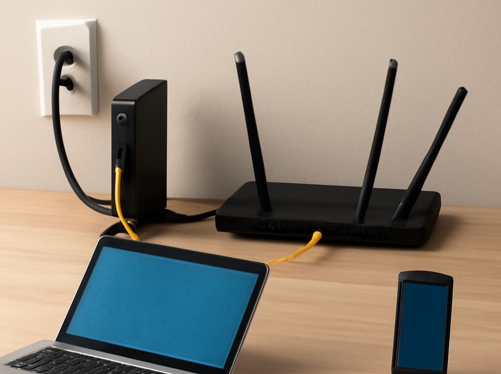
Long Ethernet Cable Runs from a Fiber Modem or ONT
A long Ethernet cable run from a fiber service can usually reach a distant room when the complete copper channel stays within 100 m. That limit includes the installed cable, outlets, connectors, and patch cords, not merely the cable measured between two devices. If the route exceeds the limit, a powered switch or a fiber uplink should extend the path instead of relying on a continuity test.
The correct starting point is the provider’s Ethernet handoff. An optical connector on an ONT is not automatically an Ethernet port, and a device sold as a fiber gateway may combine several network roles. Identifying the handoff, measuring the real pathway, and selecting the extension method prevents an otherwise well-terminated run from exceeding its media or power limits.
Identify what your fiber optic internet modem or ONT hands off
How modem, ONT, router, and media converter roles differ
A device marketed as a fiber optic internet modem may actually be an ONT, router, gateway, or media converter. These roles are related but not interchangeable:
- ONT: An optical network terminal converts the provider’s passive optical network service, such as GPON or XGS-PON, into customer-side interfaces. Its Ethernet port is commonly the usable handoff for a local network.
- Modem: A modem traditionally modulates and demodulates a service such as cable or DSL. Some providers use “modem” as a broad retail term for fiber equipment, but a fiber ONT performs the optical access conversion.
- Router: A router separates the provider network from the local network and commonly supplies NAT, DHCP, firewall functions, Wi-Fi, and multiple LAN ports. An ONT and router may be separate boxes or combined in one gateway.
- Media converter: A media converter changes one local Ethernet medium to another, such as copper RJ45 to optical Ethernet. It does not normally replace an ISP-specific ONT or authenticate directly to a PON.
The Ethernet handoff is usually an RJ45 LAN port labeled LAN, Ethernet, or a speed such as 1G or 10G. It may be on the ONT, on a separate router, or on an integrated gateway. The optical fiber entering a PON ONT is the provider-side connection and should not be treated as a standard Ethernet fiber port.
Locate the actual Ethernet demarcation before measuring the run
Trace the connection from the provider’s equipment to the first customer-owned network device. The port where Ethernet begins is the practical demarcation for a copper run. If the ONT connects to a router with a short patch cable, the long cable can generally begin at an available LAN port on the router. If the router is placed beside the distant endpoint, the long cable may instead run from the ONT’s Ethernet handoff to the router.
Confirm the port speed and network design before installation. A 1 Gb/s handoff, a 2.5 Gb/s LAN port, and a 10 Gb/s SFP+ interface may require different cable categories or transceivers. Some gateways also have dedicated WAN ports that are not interchangeable with LAN ports. The link should negotiate at the expected speed after the run is connected; a lower negotiated speed can indicate a category, termination, length, or equipment mismatch.
Plan a long Ethernet cable route within the 100 m channel limit
Count 90 m of permanent link plus 10 m of patch cords
Structured cabling standards commonly allocate up to 90 m for the permanent link and up to 10 m for combined patch cords, producing a maximum 100 m channel. The permanent link includes the cable installed through walls, ceilings, conduit, or a pathway, along with its fixed terminations. The channel adds patch cables at both ends.
For planning, measure the route through its actual pathway rather than measuring point to point on a floor plan. Include vertical rises, turns, service loops, slack at patch panels, and the distance from each outlet to its equipment. A route that appears to be 85 m may consume the available margin once patch cords and installation slack are included.
Keep the permanent link below 90 m where practical. Short, factory-made patch cords should connect the outlet or patch panel to the equipment. Avoid using a long series of couplers or patch cables to create a channel; every additional connection adds loss and another possible failure point.
Choose Cat6 or Cat6A while accounting for pathways, PoE, and temperature
Cat6 is a practical choice for many 1 Gb/s installations and can support some higher-speed applications over shorter distances. Cat6A provides more headroom for 10 Gb/s operation over a full 100 m channel and generally offers stronger control of alien crosstalk. The installed cable, jacks, patch panel, and patch cords should be rated for the target category as a complete channel.
Cable category does not cancel the channel limit. A higher-category copper cable still requires a compliant 100 m channel for standard Ethernet operation. Conversely, a lower link speed may work over a marginal or improperly installed route, but that does not make the installation standards-compliant.
Plan the pathway as carefully as the cable selection:
- Use cable with the correct jacket rating for the space, such as plenum-rated cable where required by the building pathway.
- Keep data cable separated from mains wiring and avoid long parallel runs beside power conductors. Cross unavoidable power routes at approximately a right angle.
- Respect the cable manufacturer’s bend radius and pulling tension. Do not kink, crush, staple, or sharply compress the cable.
- Use outdoor-rated or appropriately protected cable for exterior routes. Ordinary indoor cable can deteriorate from ultraviolet exposure, moisture, or temperature changes.
- Account for conduit fill, pulling access, fire stopping, and future serviceability before the cable is installed.
Power over Ethernet adds another design constraint. PoE voltage drop increases with copper length, and high-power modes create more heat in dense cable bundles. Elevated ambient temperature and tightly packed bundles can require bundle derating or a lower allowable current. The switch, endpoint, cable category, bundle size, and installation temperature should be checked against the applicable PoE and manufacturer guidance. A data link that passes at room temperature may not provide reliable power in a hot, crowded pathway.
RJ45 Ethernet connector pinout: T568A, T568B, and testing
Compare T568A and T568B color order and pair positions
The common eight-position modular plug is technically an 8P8C connector, although “RJ45” is widely used for Ethernet plugs and jacks. The ethernet connector pinout assigns each conductor to a numbered contact and preserves the twisted-pair arrangement required by Ethernet.
Viewed with the plug contacts facing the installer and the locking tab away, the conductor order is:
- T568A, pins 1 through 8: white-green, green, white-orange, blue, white-blue, orange, white-brown, brown.
- T568B, pins 1 through 8: white-orange, orange, white-green, blue, white-blue, green, white-brown, brown.
In both schemes, the blue pair occupies pins 4 and 5, and the brown pair occupies pins 7 and 8. T568A and T568B differ by exchanging the green and orange pairs. A standard straight-through link uses the same scheme at both ends: A-to-A or B-to-B. An A-to-B termination creates the historical crossover arrangement, although many modern Ethernet ports support automatic MDI-X and can correct for it.
The building’s existing standard should determine the choice. T568B is common in many commercial installations, while T568A may be specified by a local cabling standard or existing wiring. Mixing the schemes randomly is not a useful upgrade. Consistency, correct pair preservation, and compatible jacks and plugs matter more than choosing one scheme for a new isolated run.
Terminate, label, and test every pair instead of relying on continuity alone
Strip only the amount specified by the cable and connector manufacturer, keep each pair twisted as close to the termination as possible, and seat every conductor fully in the correct channel. Solid horizontal cable should use compatible jacks or plugs; stranded patch cable and solid cable may require different connector designs. Do not untwist long sections to make the conductors easier to arrange.
Label both ends with the same cable identifier and record the selected wiring scheme. After termination, test the link in stages:
- Use a wire-map tester to identify opens, shorts, crossed pairs, reversed pairs, and split pairs.
- Check the installed length and confirm that the permanent link and total channel assumptions remain valid.
- For a standards-based installation, use a qualification or certification tester rated for the target category and link type. Check insertion loss, return loss, crosstalk, and other required limits rather than only pin continuity.
- Connect the actual network equipment and verify negotiated speed, duplex, error counters, and PoE delivery where applicable.
A continuity tester can report eight connected conductors while missing excessive untwist, split pairs, poor return loss, excessive crosstalk, or a channel that exceeds the standards reach. It is therefore a basic wiring check, not proof that a long Ethernet channel will deliver its rated speed reliably.
Extend the path beyond copper with a switch or fiber
Place a switch near the endpoint when copper distance and power allow
A network switch can divide a long route into compliant copper segments. For example, an ONT or router can connect to a switch at the midpoint, and a second cable can run from that switch to the distant endpoint. Each channel still needs its own length calculation, and the switch needs suitable power and an available port.
This approach works well when a powered location already exists and both copper sections can remain within their category and PoE limits. A switch also provides additional local ports. It should not be confused with a passive coupler: a coupler does not regenerate the signal or reset the 100 m channel calculation.
When a switch is installed in a ceiling, utility area, or outdoor enclosure, temperature, ventilation, grounding, enclosure rating, and service access become part of the design. If the distant device receives PoE, the switch must supply the required standard and power budget, and the final copper segment must remain suitable for that load.
Use media converters, SFP switches, or a fiber uplink for longer routes
Fiber is usually the cleaner solution when the route has no suitable midpoint power, passes between buildings, crosses an electrically noisy area, or must extend well beyond 100 m. A typical design uses an Ethernet-to-fiber media converter at each end, or a copper switch with an optical SFP or SFP+ port at one or both ends.
Select the fiber and optics as a matched system:
- Multimode fiber, such as OM3 or OM4, is commonly used for shorter high-speed building links with compatible multimode optics.
- Single-mode fiber, such as OS2, supports longer distances when paired with the appropriate single-mode transceivers.
- Optical speed, wavelength, connector type, module coding, polarity, and link budget must match at both ends.
- The fiber pathway should protect the cable from crushing, sharp bends, contamination, and excessive pulling force.
A media converter extends an Ethernet LAN link; it does not turn a normal Ethernet transceiver into a PON ONT. The provider’s optical service should remain connected to the approved ONT, while the extension should begin at the ONT or router’s Ethernet handoff. For very long or high-bandwidth routes, an SFP/SFP+ switch pair can reduce the number of boxes and provide a cleaner upgrade path than multiple copper segments.