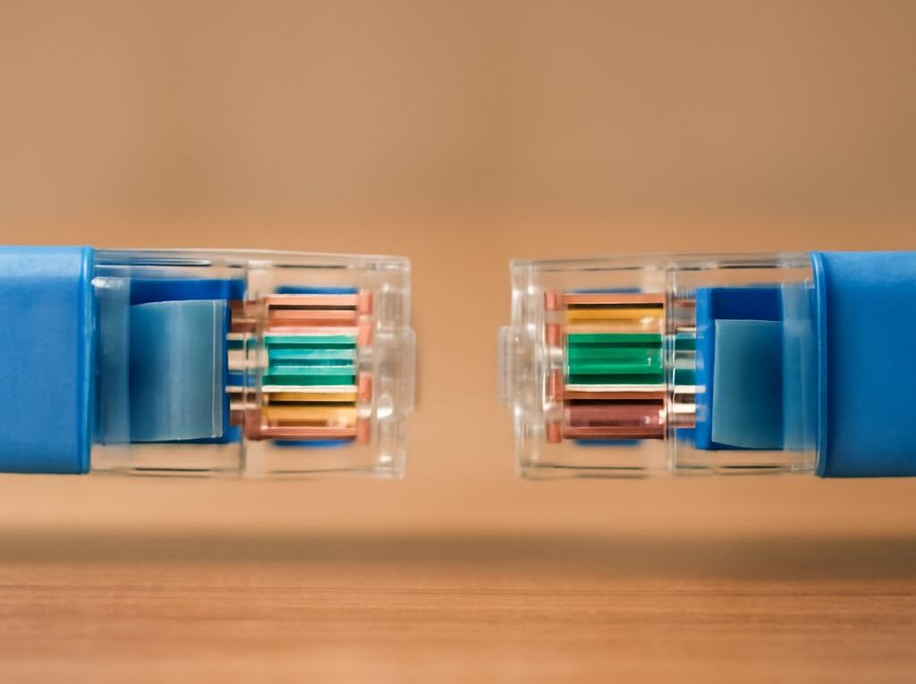
Ethernet Cable Color Meanings: How to Wire an Ethernet Jack After a Fiber Modem or ONT
Ethernet cable color meanings describe the order of the eight copper conductors on an Ethernet cable and the pairs they form. That copper wiring begins at an Ethernet port, not at the optical connector on a fiber service. A fiber optic cable modem or ONT may provide that Ethernet port, but the device and the router are not always the same unit.
To wire an Ethernet jack correctly, identify the fiber handoff, follow either the T568A or T568B color code at both copper ends, keep each twisted pair together, and test the finished run with a wire-map tester before troubleshooting internet service.
Ethernet cable color meanings: Identify the optical handoff and Ethernet demarcation
Fiber optic cable modem, ONT, media converter, or router?
The optical device and the router perform different jobs, although an ISP gateway may combine several functions in one enclosure.
- ONT: An optical network terminal converts the provider’s fiber signal into an electrical Ethernet signal. It commonly has an optical port and one or more RJ45 Ethernet ports.
- Fiber optic cable modem: This consumer term often describes an ISP gateway that accepts fiber and provides Ethernet or Wi-Fi. Technically, the optical conversion function is usually performed by an ONT or an integrated optical terminal rather than a traditional cable modem.
- Media converter: A media converter changes fiber to copper Ethernet without normally providing routing, wireless access, DHCP, or firewall functions.
- Router: A router typically connects to the ONT or media converter, receives the service on its WAN port, and provides LAN switching, DHCP, NAT, and often Wi-Fi.
- Ethernet demarcation: This is the practical handoff point where the optical service becomes copper Ethernet. The RJ45 port on the ONT or media converter is the starting point for ordinary twisted-pair wiring.
Do not apply an Ethernet copper pinout to the fiber connector. Fiber uses optical transmit and receive paths, while T568A and T568B describe eight copper conductors terminating on an RJ45-style connector or an Ethernet jack’s insulation-displacement contacts.
Example topologies from the fiber handoff to the wall jack
Common installations use one of these arrangements:
- Separate ONT and router: Fiber → ONT → Ethernet patch cable → router WAN port → router LAN or switch → wall jack.
- ONT with an integrated gateway: Fiber → ONT/router gateway → switch or patch panel → wall jack.
- Media converter and router: Fiber → media converter → Ethernet patch cable → router WAN port → switch or wall jack.
- Provider gateway with a remote switch: Fiber → gateway → structured wiring panel or switch → cable run → wall jack.
The wall jack should normally connect to a LAN port, switch, or patch-panel port after the router. Connecting it to the router’s WAN port is appropriate only when the jack is being used as the dedicated link between a separate ONT and the router.
Start copper wiring at the Ethernet port—not the fiber connector
Locate the Ethernet demarcation by following the fiber to the ONT, gateway, or media converter and finding the port labeled LAN, Ethernet, or similar. A link light or an existing Ethernet patch cable can help confirm the correct port. The in-wall cable should be solid copper Cat5e, Cat6, or better, rated for the installation location. Stranded patch cable is intended for flexible cords and is not a substitute for in-wall cable.
From that Ethernet port, trace the cable to the wall plate, structured wiring enclosure, or patch panel. If the run has two jacks, both ends must be terminated with the same wiring standard. If the provider has placed an optical connector or fiber splice inside the enclosure, leave that optical termination intact and work only on the downstream copper side.
Ethernet conductor colors and pair roles: T568A vs. T568B
T568A and T568B use the same eight conductors and the same four twisted pairs. They differ only in the positions of the orange and green pairs. Either standard can provide a straight-through Ethernet link when used consistently at both ends. T568B is common in many existing residential and commercial installations, but matching the established standard is more important than choosing one based on preference.
Pin 1–8 color order and jack orientation
The conductor order is:
- T568A: 1 white/green, 2 green, 3 white/orange, 4 blue, 5 white/blue, 6 orange, 7 white/brown, 8 brown.
- T568B: 1 white/orange, 2 orange, 3 white/green, 4 blue, 5 white/blue, 6 green, 7 white/brown, 8 brown.
On the rear of a keystone jack, follow the printed T568A or T568B color legend rather than assuming that the leftmost slot is pin 1. Jack manufacturers arrange IDC terminals differently. For an RJ45 plug, use the numbered pin view supplied with the plug or tester; do not reverse the order because the plug is being viewed from the opposite side.
The pair roles remain consistent:
- Blue pair: pins 4 and 5 in both standards.
- Brown pair: pins 7 and 8 in both standards.
- Orange and green pairs: pins 1 and 2 plus pins 3 and 6, with their positions exchanged between T568A and T568B.
Traditional 10/100-megabit Ethernet uses pins 1, 2, 3, and 6. Gigabit Ethernet uses all four pairs, so a cable can appear to work at 100 Mbps while still having a termination problem that prevents a 1 Gbps link.
Keep each twisted pair together
Each solid conductor must remain paired with its matching striped conductor. Do not arrange wires by alternating color families or by making the cable look symmetrical. A split pair can pass a basic continuity check while creating excessive interference and unreliable high-speed operation.
Untwist only the amount required to reach the IDC terminals. Keeping the twists close to the termination preserves the cable’s performance. As a practical limit, keep untwisted wire to about 13 mm (1/2 inch) or less where the jack allows it, and follow the jack manufacturer’s instructions. Maintain the cable’s bend radius and avoid sharp bends, staples, or tight compression near the wall plate.
How to wire an Ethernet jack: Punch down the wall jack
Choose the matching T568A or T568B label
Before cutting the cable, determine which standard is used at the other end. If the opposite termination is accessible, inspect its label or compare the conductor positions with the two pinouts above. If the existing installation is entirely new, select one standard and use it at both ends; T568B is often the simplest choice when no other wiring needs to be matched.
- Prepare the cable. Remove only enough outer jacket to reach the jack’s IDC terminals. Avoid nicking the insulation on the individual conductors. Separate the four pairs without pulling them farther back than necessary.
- Open the jack’s wiring area. Identify the printed T568A and T568B legends. Select the same row used by the other end of the cable.
- Place the conductors. Route each striped and solid wire into its matching color-coded slot. Keep the pair twists close to the termination and do not cross conductors unnecessarily.
- Punch down each wire. Use a compatible punchdown tool to seat the conductor fully in the IDC contact. If the tool has a cutting edge, orient it as directed by the jack manufacturer so excess wire is trimmed on the waste side.
- Inspect the termination. Each conductor should be fully seated, with no loose strand, exposed nick, or wire placed in the wrong color slot. Confirm that the orange and green pairs were not swapped accidentally between standards.
Seat conductors, add strain relief, and label the run
The cable jacket, not just the individual wires, should be held by the jack’s strain-relief feature. Keep the jacket close enough to the IDC block that movement of the cable does not pull on the punched-down conductors. Snap on the jack’s cap or close its cable clamp if supplied, then mount the jack without crushing or sharply bending the cable behind the wall plate.
Label both ends with the same identifier, such as Office-02. Label the matching patch-panel port or switch port as well. A clear label prevents a correctly wired jack from being mistaken for an inactive service port during later testing.
If a plug must be fitted to the other end, use a connector designed for the cable’s conductor type and category. Arrange the wires in the selected T568A or T568B order, keep the outer jacket inside the plug’s strain-relief area, and verify that the plug’s contacts reach the conductors evenly. A factory-made patch cable is usually more reliable for the short connection from an ONT, router, or switch to a wall jack or patch panel.
Patch, test, and verify service at the wall jack
Run a wire-map and link-speed test
Disconnect active equipment before testing the permanent cable with a basic cable tester. Connect the tester’s main unit to one end and its remote unit to the wall jack or far-end port. A correct wire map should show conductors 1 through 8 in the expected order, with no open, short, reversed pair, crossed pair, or split pair.
A continuity-only tester may not identify every split-pair fault, so use a tester that reports pair mapping when possible. If the result is wrong, recheck the selected T568A or T568B legend, the pin order, and the seating of the blue and brown pairs. A single wire in the wrong slot can produce a link at a lower speed or no link at all.
After the wire map passes, connect a known-good patch cable from the wall jack to a computer, access point, or switch. Check the negotiated link speed:
- 1 Gbps or higher: The equipment is using all four pairs when the devices support that speed.
- 100 Mbps: The service or network device may be limited to 100 Mbps, or one pair may be incorrectly terminated or damaged.
- No link: Check the patch cable, wall-jack termination, remote port, and router or switch status.
Confirm connectivity from the router or gateway
Once the physical link is active, confirm that the endpoint receives an IP address from the intended router or gateway. Test in this order:
- Check the device’s Ethernet link light and negotiated speed.
- Confirm that it received an IP address, subnet mask, gateway, and DNS settings.
- Ping the local router or gateway to verify the LAN path.
- Test DNS resolution and then open an external website to verify internet access.
If the device has a link but no IP address, the copper termination is probably functional; investigate the switch port, VLAN, DHCP service, or router configuration. If a computer works when connected directly to the router but not through the wall jack, focus on the in-wall cable, jack, patch-panel port, and patch cords. If the ONT’s Ethernet port has no service even with a known-good direct patch cable, the issue is upstream of the wall jack and should not be addressed by changing the T568A or T568B copper wiring.