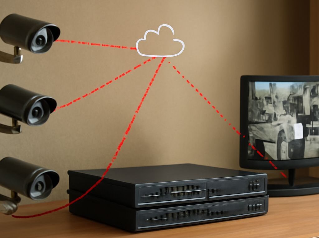
How a Network Camera Connects to a Viewing System
A camera can appear online in a management console while its live picture remains blank. Conversely, an existing stream may continue while the management connection is unavailable. For cameras connected to a network, these outcomes point to different parts of the system: the path used to configure the device and the path carrying video must each work.
From camera to application
A network camera captures and encodes video, then sends it over an IP connection to a recorder, video management system (VMS), or another authorized client. At a remote site, the camera may connect by Ethernet to a switch, which connects to a cellular router. The router provides a route across a private connection or VPN to the organization’s viewing infrastructure. A local recorder may receive the stream first and send selected video onward, depending on the design.
Each network camera needs power as well as connectivity. An Ethernet installation may use Power over Ethernet if both equipment and power budget support it; other installations use a separate supply. The device also needs an IP address, subnet, gateway, and, when names are used, DNS settings appropriate to its network. DHCP can supply these settings, while a reservation or managed static address can help a VMS consistently find the device.
Management and video use different paths
Management functions include discovering the device, authenticating, changing settings, and checking status. Video delivery uses a stream profile and a transport supported by both camera and client. For example, an integration may obtain a stream address through a management service and establish a session using RTSP. The media may then use the configured transport. ONVIF’s media specification describes profiles that connect sources and encoders to streaming settings.
A successful login or status check for an IP camera therefore does not prove that the media session can cross the same firewall, VPN, or network address translation boundary. The client may contact a different address or port for video, and an advertised private address may be unreachable from the client. Map the actual initiator, destination, protocol, and ports for each leg before changing network rules.
Check a remote site
Suppose a depot has two cameras on the local network and a cellular router connecting the site to a central VMS. Start at the camera side: verify power and link status for each networked camera, confirm each assigned address and gateway, and compare them with the VMS configuration. From an authorized device on the same subnet, test access to the camera’s management interface and its configured stream. This separates a local camera or switch problem from a problem across the remote link.
Next, check whether the VMS can reach the expected addresses through the VPN. Compare its connection logs with router and firewall logs at the time of a failed session. A ping can help test basic reachability where permitted, but a reply does not establish that the stream service is reachable or that the client can authenticate and decode it. Use the vendor’s approved stream test and the actual media profile to check that path.
Allow capacity for the stream
The bandwidth needed by cameras on a network varies with codec, resolution, frame rate, scene activity, and bitrate settings. Two illustrative 2 Mbps streams require roughly 4 Mbps before protocol overhead and other traffic; variable-rate video may rise during busy scenes. Check the site’s available uplink under normal and peak use, including other applications and simultaneous viewers. Multiple unicast streams can increase demand if they cross the same link separately.
Measure sustained throughput, loss, and latency while video is requested, then compare them with observed stream rates. If capacity is tight, consider a lower-bitrate profile or local recording with selective remote viewing, subject to the organization’s image-quality and retention needs. Axis’s network troubleshooting guidance discusses the effect of constrained bandwidth on video.
If management works but the picture is missing, test the same stream locally and then from the VMS; use the first point of failure to inspect the relevant service, route, and firewall logs.