Ethernet Cable Speeds: Choose Shielded Cat6 or SFP
Ethernet cable speeds should be matched to the required data rate, distance, and installation environment. Cat5e is usually sufficient for 1 Gb/s and many 2.5 Gb/s links, Cat6 provides more margin and can carry 10 Gb/s over shorter runs, while Cat6A is the standard copper choice for 10 Gb/s up to 100 meters. An SFP-based fiber link becomes more suitable when the run exceeds copper limits, crosses electrically noisy areas, or needs a specific optical interface.
Shielding and SFP connections solve different problems. Shielded Cat6 remains a copper Ethernet cable with the same category performance limits as unshielded Cat6; an SFP is a removable transceiver module that connects a network device to copper or fiber media through an SFP cage.
What Ethernet cable speeds can Cat5e, Cat6, and Cat6A deliver?
The following are practical planning limits for a standards-compliant permanent link and channel:
- Cat5e: Commonly supports 1000BASE-T at 1 Gb/s to 100 meters. It can also support 2.5GBASE-T to 100 meters in suitable installations, and 5GBASE-T may work to 100 meters when cable quality, bundling, and installation conditions meet the applicable requirements.
- Cat6: Supports 1 Gb/s to 100 meters and is a good choice for 2.5 Gb/s and 5 Gb/s upgrades. It can support 10GBASE-T over shorter distances, commonly about 37 to 55 meters depending on alien crosstalk, bundle size, and the installation environment.
- Cat6A: Supports 10GBASE-T to 100 meters and provides greater protection against crosstalk than Cat6. It is generally the preferred copper category for new 10 Gb/s horizontal cabling.
These figures describe Ethernet link capability, not merely the frequency printed on the cable jacket. Cat5e is rated to 100 MHz, Cat6 to 250 MHz, and Cat6A to 500 MHz, but the network devices, terminations, patch cords, and installation quality must all support the selected rate.
The 100-meter copper limit normally consists of up to 90 meters of permanent link cable plus up to 10 meters of patch cords. Long patch cords, poor terminations, tight bends, excessive bundling, and untwisting pairs too far at the connector can reduce the usable margin. A link may establish at a lower speed when it cannot reliably meet the target rate, but that fallback does not confirm that the cabling is suitable for sustained operation.
For a typical office connection, Cat5e or Cat6 is adequate for 1 Gb/s at distances up to 100 meters. Cat6 adds useful headroom for multi-gigabit access points, workstations, and switches. Cat6A is the safer selection for new 10 Gb/s runs, data-center copper links, or installations expected to remain in service through multiple equipment upgrades.
Shielded Cat6: construction, grounding, and interference
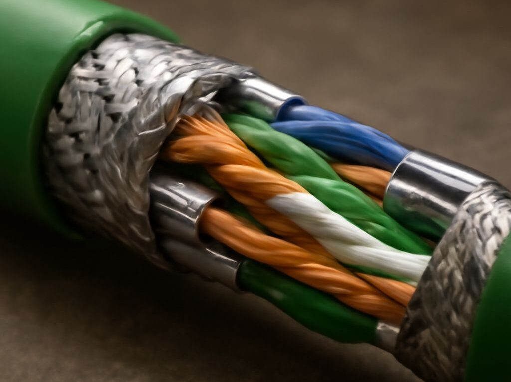
Shielded Cat6 uses a conductive layer to reduce electromagnetic interference and limit unwanted coupling between cable pairs or nearby cables. The construction varies:
- F/UTP uses an overall foil shield around otherwise unshielded twisted pairs.
- S/FTP uses a braided overall shield and individual foil shields around the pairs.
- U/FTP shields each pair with foil but has no overall braid.
Shielding can be useful near motors, variable-frequency drives, generators, fluorescent lighting equipment, radio transmitters, industrial machinery, or dense cable pathways. It can also help control alien crosstalk in high-density installations. It does not automatically increase the Ethernet speed rating. Shielded Cat6 is still Cat6, so it does not become a 100-meter 10 Gb/s medium simply because a foil or braid has been added.
The shield must form a continuous, bonded path through the cable, plugs, jacks, patch panels, and equipment ports. A shielded Cat6 installation normally requires compatible metal connectors and patch hardware, plus bonding to the telecommunications grounding system in accordance with local electrical requirements and the cabling manufacturer’s instructions. The network equipment chassis and rack bonding arrangement also matter.
Improper grounding can make shielding ineffective and can create unwanted current paths. A cable with a disconnected drain wire, an unshielded patch panel, or a shielded plug fitted incorrectly may provide little interference protection. Grounding only one part of an otherwise shielded channel can also interrupt shield continuity. The installation should therefore be designed as one complete shielded system rather than assembled from isolated shielded components.
For a normal office with short, well-separated cable runs, unshielded twisted pair is often simpler and fully adequate. Shielded Cat6 earns its place when measured or expected interference, high cable density, or equipment specifications justify it and when the installer can maintain shield continuity and correct bonding from end to end.
How the SFP connector, cage, and fiber path fit together
An SFP connection has three separate parts that are often confused:
- The SFP cage is the electrical socket built into a switch, router, firewall, server adapter, or media converter.
- The SFP module is the removable transceiver inserted into that cage. It converts the device’s electrical signals into copper or optical signals.
- The cable connector is the plug that attaches to the front of the module. Fiber modules commonly use a duplex LC connector, while other designs may use a different connector or a parallel-fiber interface.
There is no single universal “SFP connector” for every link. The cage and module must be compatible, and the module’s external connector must match the cable. A 1 Gb/s SFP, 10 Gb/s SFP+ module, and 25 Gb/s SFP28 module are different interface classes. Some equipment supports backward-compatible modules, but compatibility depends on the cage, firmware, optical standard, and manufacturer. A module should not be selected by physical fit alone.
For an optical link, match the following specifications at both ends:
- Speed and Ethernet standard: For example, 1000BASE-SX, 1000BASE-LX, 10GBASE-SR, or 10GBASE-LR.
- Wavelength: Common multimode 10 Gb/s optics use 850 nm, while many single-mode designs use 1310 nm or 1550 nm.
- Fiber type: Multimode OM3 or OM4 and single-mode OS2 are not interchangeable choices for every module.
- Reach: The module’s rated distance must cover the installed path, including patch panels and cross-connects.
- Connector and polarity: Duplex LC modules require the correct two-fiber polarity. BiDi modules use one fiber but must be installed as a matched wavelength pair.
- Peer-device support: Both modules and their host devices must support the same rate and signaling standard.
SFP does not always mean fiber. A 1000BASE-T SFP can provide a copper RJ45 port, and some SFP+ modules support 10GBASE-T or a direct-attach copper cable. These options still require host-device compatibility and have their own distance, power, and thermal limits. A fiber SFP should be chosen when optical reach, electrical isolation, or immunity to electromagnetic interference is the main requirement.
Choose and test the complete link from end to end
Start with the application and distance, then select the medium:
- For 1 Gb/s to 100 meters: Use compliant Cat5e, Cat6, or Cat6A copper. Cat6 is a practical upgrade when additional margin or future multi-gigabit support is useful.
- For 2.5 or 5 Gb/s: Check the switch and endpoint specifications, then verify the existing Cat5e or Cat6 channel. Cable age, bundling, patching, and termination quality can determine whether the intended rate is stable.
- For 10 Gb/s copper: Use Cat6A for a full 100-meter channel. Cat6 may be suitable for a shorter, properly designed run after its expected alien-crosstalk environment has been considered.
- For longer distances or strong EMI: Use an SFP, SFP+, or SFP28 optical path when the host equipment supports it. Select matching modules, fiber, wavelength, connector, and reach at both ends.
- For electrically noisy areas with copper equipment: Consider shielded Cat6 only when the entire channel can be installed with compatible shielded hardware and correct bonding. Shielding that is incomplete or incorrectly grounded should not be treated as an improvement.
Test copper after termination with a cable certifier appropriate to the target category and speed. The test should check wire map, length, insertion loss, return loss, near-end crosstalk, and other applicable performance parameters. Shielded channels should also be checked for shield continuity and bonding. A basic link light or negotiated speed is not a substitute for certification.
Test fiber by inspecting and cleaning every connector, confirming polarity, and measuring insertion loss with a light source and power meter or an equivalent certification system. Verify that the measured loss is within the optical budget of the installed modules. After activation, check the negotiated rate, interface errors, optical diagnostics where available, and stability under normal traffic. The complete link passes only when the cable or fiber, terminations, modules, cages, peer devices, and installation environment all support the same intended Ethernet service.