dBm to watts: Plan RF Power, Frequency, and Wireless Access
dBm to watts conversion shows how much RF power a radio produces, but it does not predict wireless range by itself. A complete design also considers frequency, antenna gain, cable and connector loss, interference, receiver sensitivity, terrain, and regulatory limits.
Those factors matter differently depending on the system. A Wi-Fi access point connects nearby, often mobile devices to a local network. Cellular 5G connects user equipment to an operator’s radio network and core. Fixed wireless broadband uses a radio link between fixed locations to provide an internet or private-network connection.
dBm to watts: Convert RF power and interpret the result
dBm is a logarithmic unit that expresses power relative to 1 milliwatt. Watts is an absolute power unit. The same RF output can therefore be written in either unit, but dBm is more convenient for adding gains and losses in a link budget.
Apply the dBm to watts formula with worked examples
The conversion from dBm to milliwatts is:
Power in milliwatts = 10(dBm ÷ 10)
To express the result in watts, divide milliwatts by 1,000:
Power in watts = 10((dBm − 30) ÷ 10)
The subtraction of 30 accounts for the difference between 1 watt and 1 milliwatt on a logarithmic scale. Representative values are:
- 0 dBm = 1 mW = 0.001 W
- 10 dBm = 10 mW = 0.01 W
- 20 dBm = 100 mW = 0.1 W
- 30 dBm = 1,000 mW = 1 W
- 33 dBm ≈ 2,000 mW = 2 W
For example, a radio specified at 17 dBm has an output of:
10((17 − 30) ÷ 10) = 10−1.3 ≈ 0.050 W
That is approximately 50 mW. A radio specified at 27 dBm produces approximately 0.50 W, while 37 dBm produces approximately 5 W. Every 10 dB represents a tenfold change in power. A 3 dB increase is approximately a doubling of power, and a 3 dB reduction is approximately a halving.
Negative values are normal in receiver specifications. For example, −30 dBm equals 0.001 mW, or 1 microwatt. A received signal such as −70 dBm is much weaker than a transmitter output of 20 dBm, because the signal loses energy as it travels and encounters system losses.
Transmit power must also be identified precisely. Conducted power is the output measured at the radio connector. Effective isotropic radiated power, or EIRP, includes antenna gain and subtracts losses between the radio and antenna:
EIRP in dBm = conducted transmit power + antenna gain − cable and connector loss
For example, a 20 dBm radio connected to a 6 dBi antenna through 2 dB of cable and connector loss has an approximate EIRP of 24 dBm. That is not the same as a 24 dBm radio output. The distinction matters when checking equipment specifications and regulatory limits.
Reverse the calculation with watts to dBm
The conversion from watts to dBm is:
Power in dBm = 10 × log10(power in watts × 1,000)
An equivalent shortcut is:
Power in dBm = 10 × log10(power in watts) + 30
Examples include:
- 0.1 W to dBm: 10 × log10(0.1) + 30 = 20 dBm
- 0.5 W to dBm: 10 × log10(0.5) + 30 ≈ 27 dBm
- 1 W to dBm: 10 × log10(1) + 30 = 30 dBm
- 2 W to dBm: 10 × log10(2) + 30 ≈ 33 dBm
When converting watts to dBm, the input must be RF power, not energy consumption from a power adapter. A device may draw 15 W from a PoE switch while transmitting only a fraction of a watt over the air. The remaining electrical power runs amplifiers, processors, cooling, and other circuitry.
Power figures also need a reference point. A specification might state maximum conducted output, average output, peak output, or EIRP. Channel width, modulation, antenna configuration, and local rules can cause the actual operating value to differ from a headline maximum.
How 5G frequency affects range, capacity, and link design
There is no single 5G frequency. 5G radio networks use several broad ranges, and each range trades coverage, capacity, penetration, antenna size, and deployment cost differently.
Separate frequency, antenna gain, loss, and regulation
Typical 5G planning categories are:
- Low band: below 1 GHz, often used for broad-area coverage and better building penetration.
- Mid band: roughly 1 to 6 GHz, including widely deployed capacity bands around 2.5 GHz and 3.3 to 4.2 GHz.
- High band or millimeter wave: commonly about 24 GHz and above, where very wide channels and highly directional beams can support high capacity over shorter links.
Exact bands vary by country, operator, licensing framework, and deployment. 5G is a radio access technology, not a single part of the spectrum.
At the same distance and with comparable antenna conditions, free-space path loss increases with frequency. A commonly used estimate is:
Free-space path loss in dB = 92.45 + 20 × log10(distance in kilometers) + 20 × log10(frequency in GHz)
At 1 kilometer, a 3.5 GHz signal has approximately 103.3 dB of free-space path loss. At 28 GHz over the same distance, the estimated loss is approximately 121.3 dB, or about 18 dB greater. That difference represents substantially less received power unless antenna gain or transmit conditions compensate for it.
Higher frequency does not automatically make a link impractical. A physically similar antenna can provide more directional gain at a shorter wavelength, and a compact high-frequency antenna array can form narrow beams. The trade-off is that the beam requires more accurate alignment and is more vulnerable to blockage by buildings, trees, vehicles, and sometimes heavy rain.
Lower frequencies generally diffract around obstacles and penetrate some materials better, but they offer less available spectrum in many markets and require physically larger antennas for comparable directional performance. Mid-band frequencies often provide a practical balance between coverage and capacity.
Other factors can dominate the result:
- Antenna gain: Focuses energy in selected directions and improves the link in those directions, but does not create power from nothing.
- Cable and connector loss: Removes part of the radio output before it reaches the antenna. Long cable runs are especially costly at higher frequencies.
- Polarization and alignment: Mismatched polarization or poorly aimed directional antennas can introduce significant loss.
- Obstacles and Fresnel clearance: A mathematically visible path can still perform poorly when terrain, roofs, or trees intrude into the Fresnel zone.
- Interference and noise: A strong signal may deliver poor service if competing transmissions raise the noise floor.
- Regulation: Rules may limit conducted power, EIRP, power spectral density, channel width, outdoor use, or antenna combinations.
Estimate usable range with a link budget—not transmit power alone
A link budget estimates received power by adding gains and subtracting losses:
Received power = transmit power + transmit antenna gain + receive antenna gain − path loss − other losses
All terms should be in dB or dBm. If the calculation starts with EIRP, the transmit antenna gain and transmitter-side losses have already been included and should not be added again.
For example, consider a 3.5 GHz link over 1 kilometer:
- Transmitter EIRP: 23 dBm
- Receive antenna gain: 10 dBi
- Free-space path loss: approximately 103.3 dB
- Additional connector, polarization, and implementation loss: 2 dB
The estimated received level is:
23 + 10 − 103.3 − 2 = −72.3 dBm
If the receiver requires −82 dBm for a selected low-rate mode, the nominal margin is about 9.7 dB. If the required level for a higher-throughput mode is −68 dBm, the same link does not meet that target. A design therefore needs a target data rate, channel width, modulation mode, and fade margin rather than a single range claim.
Fade margin allows for changing conditions such as rain, foliage, multipath, temperature, or temporary interference. The necessary margin depends on the link’s availability target and environment. A short indoor link can tolerate different conditions from a provider’s fixed wireless connection expected to remain usable during seasonal weather.
This is why increasing transmitter power is not a complete range strategy. A higher setting may be limited by regulation, increase interference, fail to improve the return path, or leave the receiver blocked by an obstacle. Better antenna placement, clearer Fresnel clearance, lower-loss cabling, a different frequency, or a narrower channel can produce a more useful improvement.
How an access point provides local wireless coverage
An access point provides a radio interface between wireless client devices and a wired local network. In a typical topology, phones, laptops, cameras, scanners, or sensors connect over Wi-Fi to the access point; the access point connects by Ethernet to a switch, router, firewall, or controller; and that network connects to an internet or private-service uplink.
Compare Wi-Fi access points with cellular 5G access
Wi-Fi access points and cellular 5G radios both use radio waves, but they serve different network roles.
- Topology: A Wi-Fi access point is usually a local star: several nearby clients associate with one fixed radio. Cellular 5G uses user equipment to a provider-operated cell site, which connects through transport equipment to a 5G core.
- Equipment: A Wi-Fi installation commonly uses an access point, Ethernet cabling, PoE, switching, and a local router or firewall. Cellular 5G uses a handset, modem, or customer-premises equipment with a SIM or eSIM, plus the operator’s radio, transport, and core infrastructure.
- Mobility: Wi-Fi supports local movement and roaming between access points, but associations are managed within the site’s WLAN design. Cellular 5G is designed for wider-area mobility and handovers between cells.
- Spectrum: Wi-Fi commonly operates in unlicensed 2.4, 5, and 6 GHz bands, subject to local rules and contention. Cellular 5G usually uses licensed spectrum, although shared and unlicensed arrangements also exist.
- Service path: Wi-Fi normally hands traffic to the customer’s local LAN and internet connection. Cellular 5G carries traffic through the operator’s access network and core before reaching the public internet, a private network, or an enterprise service.
A cellular 5G router placed inside a building can look similar to a Wi-Fi gateway, but its upstream connection is different. It may receive 5G from a cell site and then distribute local Wi-Fi. In that arrangement, the gateway contains both a cellular modem and a local Wi-Fi access point; the two radio functions should not be confused.
Plan topology, equipment, mobility, and service path
Local access-point planning begins with the client environment. The important questions are where users and devices will operate, what walls or machinery separate them from the radio, how much capacity each area needs, and where Ethernet or fiber can provide the uplink.
An access point typically contains one or more radios, antennas, processing hardware, Ethernet ports, and power circuitry. Indoor models often use integrated omnidirectional or sector-like antennas. Outdoor models may use weatherproof enclosures and more directional antennas. A controller or cloud management platform can coordinate channels, transmit settings, authentication, firmware, and roaming, but it does not remove the need for suitable radio placement.
Coverage and capacity are separate design goals. A signal can reach a distant client while being too weak for the required data rate. Conversely, a high signal level does not guarantee capacity if many clients share the channel or if interference is high. Transmit settings should be balanced between the access point and client devices because a powerful access point cannot compensate for a weak client return path.
For a local WLAN, the service path should be traced from the client through the access point, switch, routing and security devices, and the internet or application server. This identifies whether a problem is radio coverage, authentication, switching, routing, backhaul, or the external service rather than treating every fault as an RF-power issue.
How fixed wireless broadband connects fixed locations
What is fixed wireless internet?
What is fixed wireless internet? It is broadband delivered over a radio connection between a provider’s fixed network location and a customer site that remains in a defined place. It is commonly used as a last-mile alternative where fiber, cable, or DSL is unavailable, delayed, or more expensive to build.
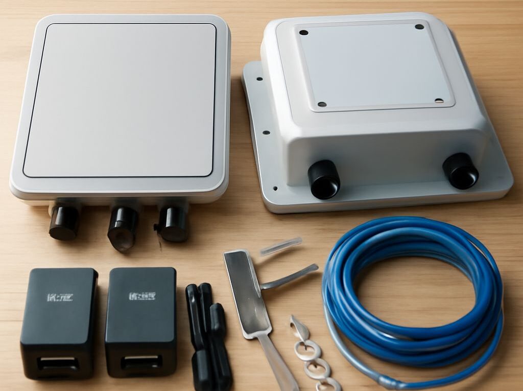
The customer normally receives an outdoor customer-premises unit, often with an integrated directional antenna, and an indoor power injector or gateway. The outdoor unit points toward a provider tower, rooftop, or other serving radio. The gateway then supplies Ethernet or local Wi-Fi inside the premises.
Fixed wireless broadband can use several topologies:
- Point-to-multipoint: A tower sector serves multiple customer-premises units. Sector capacity is shared, and each installation must meet the provider’s coverage and signal criteria.
- Point-to-point: Two dedicated directional radios connect separate buildings, towers, or network sites. This is common for enterprise backhaul and can provide a more controlled link than a shared sector.
- 5G fixed wireless access: A provider uses 5G radio technology to serve a fixed home or business CPE. The access radio and core are cellular, but the customer endpoint is intended to remain at one location.
Fixed wireless does not require the customer to use a mobile handset, although the provider may use cellular technology. The defining feature is the fixed service endpoint and the provider-managed radio path, not a particular frequency or brand of equipment.
Trace the service path and compare fixed links with Wi-Fi and cellular 5G
A typical fixed wireless service path is:
- The internet, private WAN, or content network sends traffic into the provider’s core and aggregation network.
- Fiber, microwave, or another transport system carries traffic to the serving tower or radio site.
- A sector radio or point-to-point radio transmits across the air to the customer-premises unit.
- The customer unit passes traffic over Ethernet, often through PoE, to an indoor router or provider gateway.
- The gateway delivers service to wired devices and may operate a separate local Wi-Fi network.
This path distinguishes fixed wireless broadband from a normal access point. A local access point is the final radio hop inside a customer or business LAN. Fixed wireless is generally the provider’s access or last-mile hop between sites. The indoor gateway may include an access point, but that component serves local devices after the fixed radio link has reached the premises.
Fixed wireless also differs from ordinary cellular mobility. A cellular phone can move among cells and use handovers while maintaining service. A fixed CPE is installed, aimed, and provisioned for one location. A 5G fixed wireless provider may use the same type of base station and core as mobile service, but the customer’s service qualification depends on the address, antenna direction, cell capacity, and link conditions.
Installation planning therefore focuses on tower height, obstruction clearance, Fresnel-zone protection, antenna alignment, mounting stability, cable length, grounding, weather exposure, and power availability. In high-frequency systems, rain and foliage can have a larger effect. In lower-frequency systems, interference, sector loading, and available channel bandwidth may be more important.
The final service rate is determined by more than the RF conversion or advertised transmitter power. It depends on received signal level, signal-to-noise ratio, channel width, modulation, retransmissions, shared-sector demand, backhaul capacity, and the provider’s service profile. A reliable fixed link is one whose complete link budget and service path meet the required throughput and availability at the customer’s actual location.