Fiber Modems, Optical Cable Types, and Ethernet Patch Cables: A Connection Guide
Fiber modems are commonly used as a broad term for equipment at the boundary between an optical service and a local network, but the exact device may be an ONT, an Ethernet media converter, or a gateway with several functions combined. The correct choice depends on the provider handoff: a passive optical network usually requires an ONT, while a private Ethernet fiber link can use compatible transceivers or a media converter.
After the optical handoff, most installations finish with ordinary copper Ethernet. Choosing the right fiber mode, optical grade, connector, transceiver, and copper cable prevents mismatched links and makes troubleshooting more direct.
Fiber modems: separate ONT and media-converter roles
An ONT is the usual termination for a fiber broadband service delivered over PON. ONT means optical network terminal. It communicates with the provider’s optical line terminal using technologies such as GPON or XGS-PON, handles registration and service-specific signaling, and presents one or more customer interfaces. Those interfaces may include Ethernet, telephone, television, or management functions.
An ONT can be a small fiber box, part of an ISP gateway, or an integrated unit that also performs routing, Wi-Fi, firewall, and DHCP functions. The provider normally determines which ONT models and optical characteristics are approved because the device must match the PON technology and service profile. Replacing it with a generic optical converter usually does not work.
The term fiber modem is less precise. It may describe an ONT in consumer support material, even though PON equipment does more than a traditional cable or DSL modem. It can also describe a device that converts an optical Ethernet signal to copper Ethernet. The product label alone is therefore not enough to identify its role.
A media converter performs a narrower job in most networks: it changes one physical Ethernet medium into another, such as fiber into copper RJ45 Ethernet. It does not normally register with a GPON or XGS-PON provider system, authenticate a subscriber on the optical access network, or provide routing. A typical private-network example is a switch with an SFP slot connected by fiber to a media converter that presents copper Ethernet to a server or camera.
Common optical handoffs include:
- Provider PON handoff: The service fiber enters an ONT. The ONT supplies Ethernet to a router or directly to a customer firewall, depending on the provider’s design.
- Provider active-Ethernet handoff: The provider may deliver an Ethernet circuit through an optical network interface, SFP port, or managed demarcation device. This is not automatically the same as a PON ONT.
- Private fiber link: Two switches, a switch and a server, or two buildings may use matching SFP or SFP+ transceivers. A media converter can be used when one endpoint has only copper Ethernet.
- Integrated gateway: One enclosure may contain the ONT, router, Wi-Fi access point, and sometimes voice hardware. Its combined appearance does not make every internal function interchangeable with a separate converter.
To identify the required equipment, check whether the service is GPON, XGS-PON, active Ethernet, or a private optical link; identify the connector and wavelength; and confirm whether the endpoint expects a provider-authorized ONT, a pluggable transceiver, or standard Ethernet. The device should be selected before the cable because the optical interface determines the required fiber and optics.
Types of fiber optic cable: compare mode, grade, and reach
The primary fiber choice is between single-mode and multimode. Mode describes how light travels through the core. It is not the same as cable jacket color, connector shape, or the bandwidth rating printed on a transceiver.
- Single-mode fiber: A small core, typically about 9 micrometers, carries light over one principal mode. It supports long distances and is used for ISP access, campus links, data-center interconnects, and many high-speed links. OS2 is the common modern outdoor and long-distance grade; OS1 is generally associated with tighter indoor cable construction.
- Multimode fiber: A larger core, commonly 50 or 62.5 micrometers, carries multiple light modes. It is practical for shorter building and data-center links where compatible short-reach optics are available. OM1, OM2, OM3, OM4, and OM5 describe different multimode performance grades. OM3 and OM4 are common for higher-speed short links.
Grade affects loss, bandwidth, and supported reach. OS2 single-mode cable does not automatically provide any distance unless the transceiver is also designed for that distance and wavelength. Similarly, an OM4 cable cannot make a multimode optic operate beyond its rated reach. The transceiver, cable grade, connector quality, splice loss, and link budget work together.
For example, a short switch-to-switch connection may use an 850-nanometer multimode optic with an OM3 or OM4 duplex patch cable. A building-to-building or provider connection may use a 1310- or 1550-nanometer single-mode optic and OS2 cable. These examples are common rather than universal; the optic’s data sheet and the equipment specification control the actual distance.
Fiber construction also matters. A duplex patch cord contains two fibers, normally one for transmit and one for receive. A simplex cord contains one fiber and is used where bidirectional transmission occurs over a single strand or where only one direction is needed. Indoor tight-buffered cable, outdoor loose-tube cable, armored cable, and bend-insensitive variants address different installation conditions. A patch cord should not be substituted for a permanently installed cable where the cable needs pulling strength, environmental protection, or fire-rated construction.
Connectors, transceivers, wavelength, polarity, and cleaning
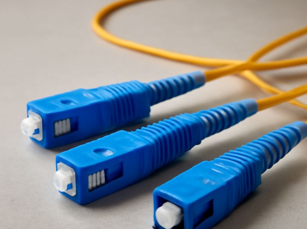
The connector must match both the equipment and the cable assembly. LC connectors are compact and common on SFP modules and data-center patch panels. SC connectors are larger push-pull connectors still found on many provider ONTs and fiber distribution points. An adapter that changes the physical shape does not correct an incompatible optic, polish type, or fiber mode.
Polish is especially important at provider interfaces. UPC connectors have a flat or slightly curved physical contact with a blue body often used for standard optical links. APC connectors use an angled polish, commonly identified by a green body, to reduce reflected light. UPC and APC connections should not be mated together. The end faces can be damaged even when the connector appears to fit.
The transceiver determines much of the optical specification. Before selecting a cable, match:
- Fiber mode: Single-mode optics require single-mode fiber; multimode optics require the appropriate multimode fiber.
- Wavelength: Common values include 850 nanometers for short multimode links and 1310 or 1550 nanometers for many single-mode links. PON systems may use different downstream and upstream wavelengths.
- Reach: A short-reach optic, such as a data-center SR module, is not a substitute for a long-reach LR or provider-specific optic.
- Speed and form factor: SFP, SFP+, SFP28, QSFP, and other modules have different electrical interfaces, rates, and equipment compatibility.
- Polarity: A duplex link must send the transmit signal from one end to the receive input at the other. Duplex A-to-B patching normally provides this crossover, but some equipment or structured cabling uses a different polarity scheme.
BiDi or simplex systems use matched transmit and receive wavelengths at opposite ends. For example, one module may transmit at 1310 nanometers and receive at 1490 nanometers, while the other reverses those functions. These modules must be purchased as a compatible pair. Two ordinary duplex modules cannot be replaced with BiDi modules without checking the optical design.
Cleaning is part of connection quality, not an optional cosmetic step. Dust on a fiber end face can raise insertion loss, create reflections, and permanently scratch a mating surface. Keep dust caps on unused ports and connectors, inspect the end face with suitable inspection equipment, and clean with a fiber-specific cleaning tool before mating. Do not touch the end face or use household cloths, alcohol wipes, or compressed air as substitutes for proper fiber-cleaning materials. Clean both sides if a link shows unexpected loss, but avoid repeatedly inserting contaminated connectors into a transceiver.
Patch cable vs Ethernet cable: what to use after the optical handoff
Ethernet cable is the broad category for copper cabling that carries Ethernet, including permanent horizontal cable and flexible patch cords. A patch cable is usually a short, factory-terminated cable intended to connect equipment to a patch panel, wall outlet, switch, router, ONT, or media converter. Therefore, a copper patch cable can be an Ethernet cable, but not every Ethernet cable is a patch cable.
After an ONT or media converter presents an RJ45 Ethernet port, the normal connection is a copper Ethernet patch cord with the required category rating. Cat5e supports ordinary gigabit links in compliant installations. Cat6 provides additional performance margin and is common for new office and home wiring. Cat6A is used when 10Gbps operation over the full 100-meter balanced-copper channel is required. The port, cable category, termination quality, and installation distance must all support the target speed.
Patch cords usually use stranded conductors. Stranded copper tolerates bending and repeated movement, making it suitable for equipment racks and desk connections, but it has somewhat greater attenuation than equivalent solid conductors. Permanent links installed in walls, ceilings, or cable trays normally use solid-conductor horizontal cable terminated on a patch panel or keystone jack. Solid cable maintains electrical performance over the installed run but is less suitable for repeated flexing.
A practical finished connection may look like this:
- The provider fiber connects to the approved ONT, or a private fiber connects to a compatible switch transceiver or media converter.
- The optical endpoint is configured with the correct mode, wavelength, connector polish, and service settings.
- An RJ45 copper patch cable connects the endpoint’s Ethernet port to a router, firewall, switch, access point, server, or computer.
- If a building contains permanent copper cabling, the endpoint patch cord connects to a wall outlet or patch panel, and a second patch cord connects the far-side outlet or panel to the network device.
Use a fiber patch cord only where the equipment has an optical port or transceiver. Use a copper Ethernet patch cord where the handoff is RJ45. If the provider’s ONT has an SC/APC optical input and an RJ45 output, the customer normally does not choose the provider-side fiber cord; the usable customer connection begins at the Ethernet output. If a private converter has an LC duplex port on one side and RJ45 on the other, the LC fiber must match the converter’s optic, while the RJ45 side uses copper Ethernet patching.
When a link fails, check the boundary in order: provider or private handoff type, transceiver compatibility, fiber mode and reach, connector polish, duplex polarity, cleanliness, and finally the copper patch cable and Ethernet port. This separates an optical mismatch from an ordinary copper patching fault.