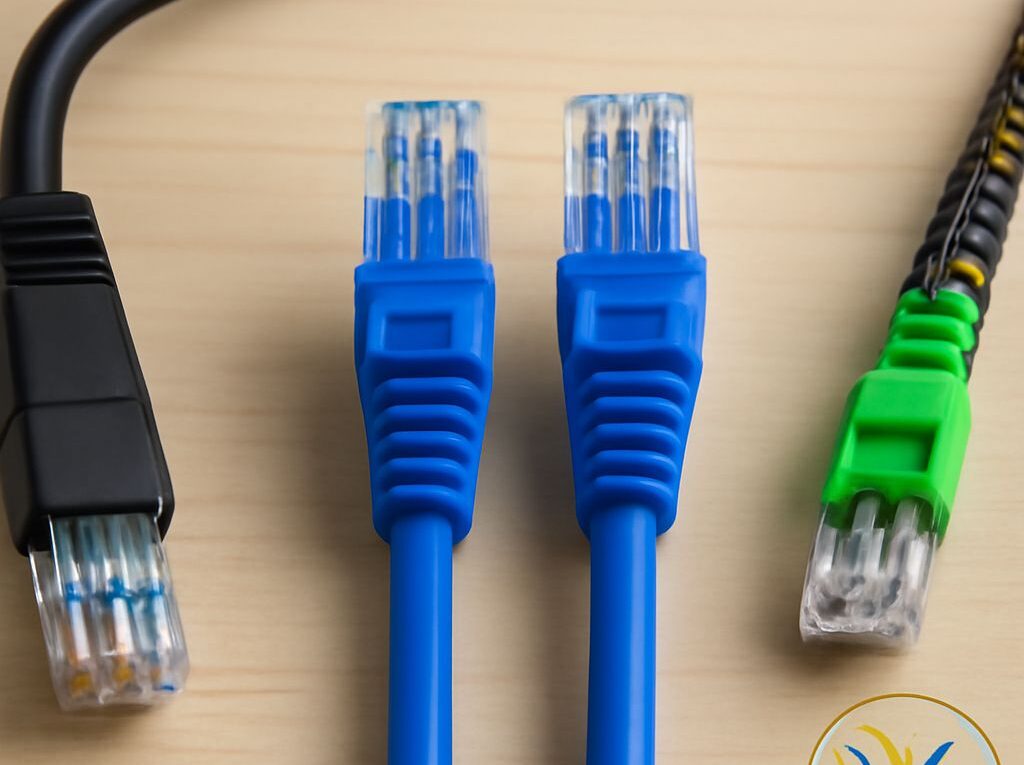
Difference Between Cat6 and Cat7 Ethernet Cables: Length, Connectors, and Wire Colors
The difference between cat6 and cat7 is not simply that one number is higher. Cat6 is the straightforward choice for most RJ45-based Ethernet installations, while Cat7 is a more specialized, shielded cabling system that depends on compatible components and proper bonding. Cat7-labeled cable terminated with ordinary RJ45 hardware may work, but it is not automatically a standards-equivalent Cat7 channel.
Both categories can support common Gigabit Ethernet applications over a 100 m copper channel when the complete installation is designed and tested correctly. The practical choice depends on the required application, connector ecosystem, shielding, installation space, and certification target.
difference between cat6 and cat7: recognized standards, speed, applications, and connectors
Cat6 is recognized in ANSI/TIA-568.2-D as Category 6 and aligns broadly with ISO/IEC Class E. Its channel and component performance is specified to 250 MHz. Cat6 supports 1000BASE-T to 100 m and can support 2.5GBASE-T and 5GBASE-T over typical structured-cabling channels. 10GBASE-T can run over Cat6, but the usual planning limit is about 55 m because of alien crosstalk and the surrounding cable environment.
Cat7 is associated with ISO/IEC Class F cabling and a 600 MHz component performance level. ANSI/TIA does not define a Category 7 tier in its balanced twisted-pair cabling nomenclature. A compliant Class F system is normally shielded and can support 10GBASE-T over a 100 m channel when the cable, connectors, patch panels, and installation all meet the required specifications.
Cat7’s 600 MHz rating does not mean an Ethernet switch will operate at 600 MHz, and it does not automatically provide a faster network. Ethernet speed is determined by the application, active equipment, channel performance, and the weakest component in the link. For a new 10GbE installation that uses conventional RJ45 switch ports, Cat6A is often the more direct standards-based selection because it is recognized by both common TIA and ISO/IEC cabling frameworks for 10GBASE-T to 100 m.
- Cat6 ecosystem: Cat6-rated 8P8C modular plugs, commonly called RJ45 plugs, jacks, keystone modules, patch panels, and patch cords are widely available and interoperable.
- Cat7 ecosystem: A standards-based Class F installation may use specialized connectors such as GG45 or TERA, along with shielded patching hardware. These connectors are not interchangeable with every ordinary RJ45 component.
- RJ45-terminated Cat7 cable: It may connect to ordinary Ethernet equipment and function for a common application, but the resulting channel is limited by its RJ45 components and must be tested against the appropriate category or class requirements.
Cat6 may be unshielded or shielded. Cat7 cabling is commonly built as S/FTP, with an individual foil around each twisted pair and an overall braid or shield. That construction improves separation from electrical noise and controls crosstalk, but it also increases cable diameter, stiffness, bend-radius requirements, termination effort, and cost.
ethernet cable lengths: 100 m channel limits and real-world reach
For standard balanced copper Ethernet, plan around a 100 m maximum channel. That total includes the fixed cable, patch-panel connections, and equipment or patch cords at both ends. A common structured-cabling model is:
- 90 m maximum permanent link: the fixed cable installed between the telecommunications room and the outlet or other termination.
- Up to 10 m of cords: the combined patch and equipment cords at both ends of the channel.
When planning ethernet cable lengths, the advertised cable-reel length is not the only measurement that matters. A 90 m horizontal run followed by 6 m of patch cable at one end and 6 m at the other creates a 102 m channel and exceeds the typical channel model. Stranded patch cords can also have different transmission characteristics from solid horizontal cable, so replacing a short cord with a much longer one can reduce the allowable fixed-link length.
Cat6 and Cat7 do not gain a longer copper reach merely because Cat7 has a higher frequency rating. Cat6 commonly supports Gigabit Ethernet to 100 m. For 10GBASE-T, ordinary Cat6 is generally planned for up to 55 m, while Cat6A and a properly implemented Class F/Cat7 channel can support 10GBASE-T to 100 m. Actual limits depend on cable construction, bundle size, temperature, connectors, and the applicable test standard.
Runs beyond 100 m require a different design rather than simply buying a longer passive copper cable. Typical options include an additional switch, a fiber link, or a purpose-built Ethernet extender. In a long building run, the path should also account for patching locations, service loops, conduit fill, bend radius, and spare capacity.
ethernet color: T568A and T568B wire order for RJ45 termination
For ethernet color conventions, T568A and T568B assign the same four twisted pairs to the same eight contacts but swap the green and orange pairs. Neither scheme is inherently faster. The important requirement is using the same scheme consistently and preserving each twisted pair as close to the termination as the connector design allows.
Looking at an RJ45-style plug with the contacts facing up, the latch underneath, and pin 1 on the left, the wire order is:
- T568A: pin 1 white/green, pin 2 green, pin 3 white/orange, pin 4 blue, pin 5 white/blue, pin 6 orange, pin 7 white/brown, pin 8 brown.
- T568B: pin 1 white/orange, pin 2 orange, pin 3 white/green, pin 4 blue, pin 5 white/blue, pin 6 green, pin 7 white/brown, pin 8 brown.
A straight-through patch cable uses T568A at both ends or T568B at both ends. A cable with T568A at one end and T568B at the other is a crossover cable. Most modern switches and network adapters use auto MDI-X, so crossover cables are rarely needed for ordinary links, but the pair assignments still need to be correct.
When terminating a wall jack or patch panel, the printed color legend on that specific component should take priority over a plug diagram. The termination method is viewed differently on a jack than on a plug. A basic continuity tester can identify an open, short, reversed pair, or split pair, but it does not prove that the link meets Cat6, Cat6A, or Class F transmission performance.
Choose the connector ecosystem: shielding, grounding, size, cost, interoperability, and channel tests
Selection should begin with the complete channel rather than the cable jacket label. Cat6 with standard RJ45 components is usually the simplest option for offices, homes, access points, cameras, phones, and Gigabit switches. Cat6A is generally the practical upgrade when 10GBASE-T to 100 m is a defined requirement. Cat7 is appropriate when a project specifically calls for a shielded ISO/IEC Class F system, specialized connectors, or additional separation from electromagnetic interference.
Shielded cabling only provides its intended benefit when the shield is continuous and correctly bonded. The cable shield must make reliable contact with shielded plugs, jacks, patch panels, and other metal hardware. Patch panels and racks should use the specified bonding method and connect to the building’s telecommunications grounding and bonding system. A shielded cable plugged into unshielded components does not create a complete shielded channel, while an improvised grounding arrangement can introduce reliability and safety problems.
Physical and financial factors also favor Cat6 or Cat6A in many installations. Cat7 cable is often larger and less flexible because of pair shields, an overall shield, separators, or larger conductors. It may need more space in conduit and cable trays, larger bend radii, shield-compatible termination tools, and more room inside boxes and patch panels. Specialized GG45 or TERA hardware is less common and usually costs more than RJ45 equipment. Cat7 cable fitted with inexpensive RJ45 ends may cost less, but that combination should not be assumed to deliver a certified Class F channel.
Interoperability depends on the connector path from the switch to the permanent cable. An RJ45 switch port normally requires an RJ45-compatible outlet and patch panel. A GG45 or TERA system requires compatible hardware or a manufacturer-approved hybrid interface. If different category or connector families are mixed, the channel is normally evaluated according to the lowest-rated or limiting component and its supported application.
For a new installation, request a certification test rather than relying only on a wire map. The test type must match the intended claim:
- Permanent-link testing checks the fixed 90 m installation, including the installed cable and consolidation or patching hardware but not ordinary user patch cords.
- Channel testing checks the complete operational path, including patch and equipment cords, up to the typical 100 m limit.
- Transmission tests can include length, insertion loss, return loss, wire map, near-end crosstalk, power-sum crosstalk, attenuation-to-crosstalk ratio, propagation delay, and delay skew.
- Shielded systems should also be checked for shield continuity and correct bonding through the installed connector ecosystem.
The certification tester should use the correct limit for the claimed Cat6, Cat6A, or Class F installation and the correct permanent-link or channel adapter. A pass result from a lower category setting does not validate a higher category claim. The final report should identify the cable type, connector configuration, test limit, measured length, and any failures that were repaired before acceptance.