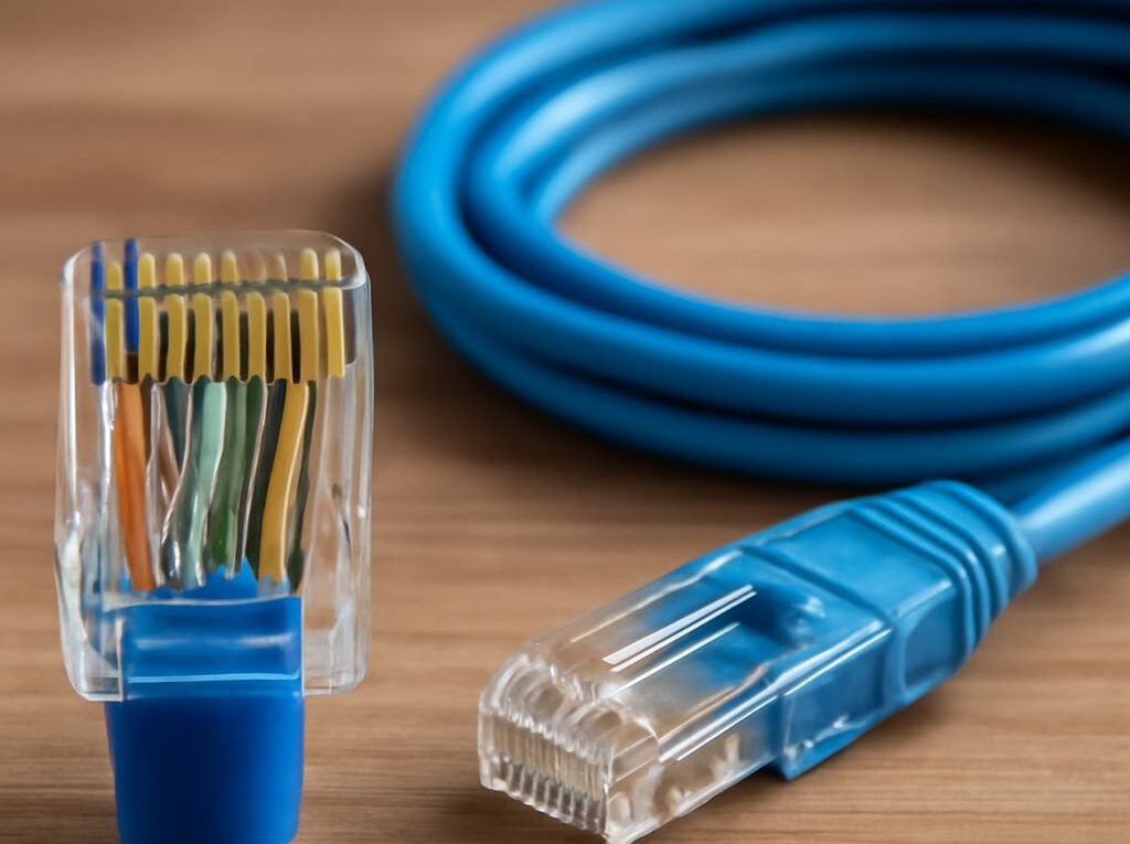
RJ45 Crimp: How to Use the Correct Ethernet Pinout
A reliable RJ45 crimp depends on three things: a compatible cable and plug, the correct conductor order, and a firm connection that captures the cable jacket. Hold the plug in the correct orientation throughout the process, because reversing the view can make an otherwise correct wiring sequence appear wrong.
This method uses either the T568A or T568B Ethernet standard. T568B is common for patch cables, but either standard works when the same standard is used at both ends. The steps below cover preparation, conductor arrangement, insertion, crimping, inspection, and cable-tester results.
RJ45 crimp: choose a compatible cable, plug, and crimper
Use an eight-position, eight-contact modular plug designed for the cable being terminated. Match the plug to the cable’s conductor type and diameter:
- Solid-conductor cable: use a plug specified for solid conductors.
- Stranded patch cable: use a plug specified for stranded conductors.
- Category rating: choose a plug rated for the cable category, such as Cat5e or Cat6.
- Conductor size: check the plug’s supported American Wire Gauge range and insulation diameter.
Solid cable is commonly used for permanent runs, while stranded cable is more flexible and suitable for patch leads. A plug designed for the wrong conductor type may not pierce the conductor reliably or may fail to hold the cable securely.
Use an eight-position modular crimper that matches the plug style. Standard plugs and pass-through plugs use different tool features. A pass-through crimper cuts the conductors flush as it crimps; a standard crimper requires the conductors to be trimmed to length before insertion. A ratcheting tool helps ensure that the contacts are fully seated.
Cut the cable square with a cable cutter. If a strain-relief boot will be used, slide it onto the cable before stripping the jacket. Do not rely on the plug’s contacts to hold the individual conductors. The rear strain-relief tab must press against the outer jacket, not the exposed wires.
RJ45 Ethernet pinout: contacts up, latch down; prepare pairs and arrange all eight colors in T568A or T568B order
For the standard front view, hold the RJ45 plug with the gold contacts facing up, the plastic latch facing down, and the cable entry pointing away from the viewer. In this orientation, pin 1 is on the left and pin 8 is on the right. Keep this view consistent when checking the conductor order.
The complete T568A and T568B sequences are:
- T568A: pin 1 white/green, pin 2 green, pin 3 white/orange, pin 4 blue, pin 5 white/blue, pin 6 orange, pin 7 white/brown, pin 8 brown.
- T568B: pin 1 white/orange, pin 2 orange, pin 3 white/green, pin 4 blue, pin 5 white/blue, pin 6 green, pin 7 white/brown, pin 8 brown.
The blue pair always occupies pins 4 and 5, and the brown pair occupies pins 7 and 8. The main difference is that the orange and green pairs exchange positions between T568A and T568B.
A useful RJ45 pin out reference must show both the pin numbers and the plug orientation. Looking at the latch side instead of the contact side reverses the apparent order and can result in a failed cable. Use T568B at both ends for a conventional straight-through patch cable unless the installation specifically requires T568A.
- Strip the jacket. Remove approximately 25 to 30 mm of outer jacket from the cable end. Use the stripping blade lightly so the twisted-pair insulation is not nicked. If a conductor has been damaged, cut the end off and start again.
- Separate the pairs. Untwist only the amount needed to arrange the conductors. Keep the twists as close to the plug as practical; for high-frequency Ethernet cabling, no more than about 13 mm of untwist should remain near the contacts.
- Arrange the conductors. Place all eight wires in the selected T568A or T568B order. Keep the sequence flat, parallel, and free of crossings. Pin 1 remains the leftmost conductor when the contacts are up and the latch is down.
- Pinch the bundle. Hold the conductors firmly between the fingers close to the jacket. This preserves the order while the tips are trimmed.
- Trim the tips square. For a standard plug, leave roughly 12 to 15 mm of straight, exposed conductor between the jacket edge and the trimmed tips. The exact length depends on the plug, so the conductors must be long enough to reach the front of every channel while the jacket reaches the rear strain-relief area.
Do not flatten the cable so aggressively that the pair conductors lose their natural grouping. The conductors should be straight enough to enter the channels, but the cable jacket should remain close enough to the plug to preserve the cable’s construction.
Insert and crimp with contacts up, latch down: set trim length, seat to full depth, and capture the jacket for mechanical strain relief
With the plug still held contacts up and latch down, slide the ordered conductors into the plug. The white-striped conductor for pin 1 must enter the leftmost channel. Push the cable forward until all eight conductor tips reach the front of the plug.
Look through the clear plastic before crimping. Each conductor should occupy its own channel, and the order should remain unchanged from left to right. No conductor should stop short, overlap another wire, or curl under the bundle. If the plug has a conductor guide, make sure every wire passes through the guide’s separate opening.
Push the cable farther into the plug until the outer jacket passes beneath the rear strain-relief tab. The jacket should be visible inside the plug behind the contact area. A correct insertion has two distinct features:
- The eight conductor tips reach the front wall or front edge of the contact channels.
- The outer jacket extends far enough into the rear of the plug for the strain-relief tab to grip it.
If the conductors reach the front but the jacket stops outside the plug, the finished cable may have continuity but poor mechanical strength. Pull the conductors back, adjust the trim length, and reinsert them. If the wires do not reach the front, the bundle was trimmed too short and the plug should be replaced after recutting the cable.
Insert the loaded plug into the matching cavity of the crimper. Confirm that the plug is fully seated and that the tool’s contact bar is aligned with the plug contacts. Squeeze the handles completely in one controlled motion. A ratcheting tool should complete its cycle before releasing the plug.
The crimping action forces the metal contacts down through the insulation into the conductors and presses the rear tab against the cable jacket. It should not crush the cable or expose additional conductor at the back. On a pass-through plug, the tool trims the wire ends during the same operation. On a standard plug, the previously trimmed ends remain inside the plug.
Do not crimp a plug twice to compensate for a poor insertion. A second compression can deform the housing or contacts. Cut off the plug, prepare a fresh cable end, and use a new plug if the jacket was not captured or a conductor was out of order.
RJ45 pinout: inspect in the same orientation for continuity, wire-map, open, short, reverse, cross, and split-pair faults
Inspect the finished plug before connecting it to equipment. Hold it with contacts up and latch down, then check the following:
- The pin 1 conductor is on the left and the eight-color sequence matches T568A or T568B.
- All eight conductors reach the front of the plug.
- The conductors remain in separate channels without crossing.
- The jacket is inside the rear of the plug beneath the strain-relief tab.
- The contacts are pressed down evenly and the housing is not cracked.
- No conductor insulation is cut back so far that bare wire is exposed behind the contact area.
Use a cable tester with a main unit and a remote unit. Connect one plug to each unit and select the wire-map or continuity function. For a straight-through cable, the expected result is pin 1 to pin 1, 2 to 2, 3 to 3, 4 to 4, 5 to 5, 6 to 6, 7 to 7, and 8 to 8. The result is the same whether both ends use T568A or both use T568B.
Testers may display faults in different formats, but the common meanings are:
- Open: one conductor has no electrical path from end to end. The wire may be too short, not fully inserted, not pierced by the contact, or broken near the plug. Reinspect that pin and the jacket position.
- Short: two or more pins are electrically connected when they should be separate. Look for crossed bare conductors, damaged insulation, a deformed contact, or a damaged plug.
- Reverse: the conductors are connected, but the order within a pair is reversed at one end. A tester may show a pair such as 1 and 2, 3 and 6, 4 and 5, or 7 and 8 exchanged. Follow the tester’s displayed pin map because labels vary by model.
- Cross: a conductor lands on the wrong pin between the two ends. A deliberate T568A-to-T568B cable commonly shows the orange and green pair positions exchanged: pin 1 maps to 3, pin 2 to 6, pin 3 to 1, and pin 6 to 2. This is a crossover arrangement, not a straight-through cable.
- Split pair: the pin numbers may appear continuous, but conductors from different physical twisted pairs have been combined. For T568B, pins 1 and 2 must be the orange pair, pins 3 and 6 the green pair, pins 4 and 5 the blue pair, and pins 7 and 8 the brown pair. A basic LED continuity tester may not detect a split pair; a tester with pair-balance or split-pair detection is required.
For a failed result, compare the tester’s map with the plug held contacts up and latch down. If the error is limited to one end, cut off that plug and repeat the conductor arrangement. If both ends show the same unexpected pattern, verify that the selected standard was used consistently and that the cable was not damaged during stripping.