Network Cable Wiring Diagram: RJ45 Pinout and Surge Protection
This network cable wiring diagram shows the RJ45 pin order, the two accepted color standards, and the separate paths for Ethernet data and surge discharge. A straight-through cable uses the same standard at both ends: T568A-to-T568A or T568B-to-T568B.
For an exposed cable entering a building, place a compatible network surge protector between the outside cable and the network equipment. The Ethernet signal passes through the protector; a separate grounding conductor directs surge energy toward the building’s approved grounding and bonding system.
RJ45 Pinout: Plug Orientation and Ethernet Pair Roles
How to read the eight pins
Hold the RJ45 plug with the gold contacts facing the viewer, the locking tab underneath, and the cable running away from the viewer. In this orientation, pin 1 is on the left and pin 8 is on the right. Count the contacts from left to right before inserting the conductors.
- Pin 1: leftmost contact
- Pins 1 and 2: one twisted pair
- Pins 3 and 6: the second twisted pair
- Pins 4 and 5: the third twisted pair
- Pins 7 and 8: the fourth twisted pair
Do not identify pins by looking at the plug from the rear or by placing the locking tab in a different position. Reversing the viewing orientation reverses the apparent pin order and commonly produces a failed wire map.
What each twisted pair carries
10BASE-T and 100BASE-TX use the pairs on pins 1-2 and 3-6. Gigabit Ethernet and faster copper standards use all four pairs: 1-2, 3-6, 4-5, and 7-8. The pairs must remain twisted as close as practical to the plug contacts because excessive untwisting increases crosstalk and can reduce link performance.
The data path and the protection path should be checked separately:
- Data path: network jack or outside cable → protector line port → protector equipment port → patch lead → switch, router, access point, or powered device.
- Protection path: surge energy → protector discharge circuit → grounding or bonding conductor → approved building grounding system.
The grounding conductor is not a replacement for any Ethernet pair. It should not be used as a signal conductor, and the protector should not be installed without its required ground connection.
Network Cable Wiring Diagram: T568A and T568B
T568A color order
With the plug held contacts-up and pin 1 on the left, the T568A pinout is:
- Pin 1: white/green
- Pin 2: green
- Pin 3: white/orange
- Pin 4: blue
- Pin 5: white/blue
- Pin 6: orange
- Pin 7: white/brown
- Pin 8: brown
The paired sequence is white/green and green, white/orange and orange, white/blue and blue, then white/brown and brown. The slash notation identifies a white conductor with a colored stripe.
T568B color order
Using the same plug orientation, the T568B pinout is:
- Pin 1: white/orange
- Pin 2: orange
- Pin 3: white/green
- Pin 4: blue
- Pin 5: white/blue
- Pin 6: green
- Pin 7: white/brown
- Pin 8: brown
T568B is common in many existing structured-cabling installations, while T568A remains an accepted standard. The important requirement is consistency. A cable terminated A-to-A or B-to-B is straight-through. A cable terminated A-to-B is a crossover cable.
Straight-through termination and wire-map faults
For a normal patch cable, choose one standard and use it at both ends. T568B at both ends is often selected when matching an existing B-standard installation, but T568A at both ends works the same way when the entire link follows A.
Common wire-map faults include:
- Reversed pair: the two conductors within one pair are exchanged, such as green on pin 1 and white/green on pin 2.
- Transposed pair: a complete pair is placed in another pair’s pin positions.
- Split pair: individual conductors have continuity to the expected pin numbers but come from different twists. A basic continuity tester may miss this; a wire-map or certification tester can identify it.
- Unintended crossover: one end uses T568A and the other uses T568B.
- Open conductor: a wire is too short, not fully inserted, or not pierced by the plug contact.
- Short or bridge: adjacent conductors touch, or a shield strand enters a contact.
Modern switches commonly support automatic MDI-X, so an unintended crossover may still establish a link. It is nevertheless a wiring error for a specified straight-through cable and can cause problems with older equipment, test results, or future changes.
Network Surge Protector Placement: Compatibility and Grounding
Place protection at the exposure point
Install the protector where the outdoor or otherwise exposed Ethernet cable enters the building, before the cable reaches a switch, router, recorder, access point, or PoE injector. Keep the unprotected cable inside the building as short as possible. The usual path is:
Outdoor cable → LINE or OUTDOOR port → surge protector → EQUIPMENT or INDOOR port → short patch lead → network equipment.
Follow the port labels because some protectors are directional. If a cable runs between two separately exposed buildings, protection may be required at both ends. A long cable in an outdoor pathway can expose equipment at either endpoint, even when only one end is near an obvious entry point.
A plug-in Ethernet protector limits surge exposure at its installation point; it does not replace a complete grounding, bonding, or lightning-protection design. Building wiring, cable routing, and the grounding system should be evaluated as a complete installation, especially for rooftop, tower, pole, or inter-building cable runs.
Check speed, PoE, shielding, and patch leads
Match the protector to the entire link rather than choosing one based only on the RJ45 connector. Check these specifications before installation:
- Category and speed: the protector should support the cable category and intended rate, such as 1000BASE-T, 2.5GBASE-T, 5GBASE-T, or 10GBASE-T. An unsuitable device can cause negotiation at a lower speed or prevent a link.
- PoE: for powered cameras, access points, phones, or other devices, verify the required IEEE PoE type, voltage, current, and all-pair operation. A data-only protector may interrupt or damage a PoE installation.
- Pair protection: gigabit and faster links require protection designed for all four pairs, not only the two pairs used by 10/100 Ethernet.
- Shielding: shielded cable requires compatible shielded connectors, jacks, patch leads, and protector construction if the shield is intended to be continuous. Do not leave drain wires or foil shields loose where they can contact signal pins.
- Patch leads: use short, correctly rated leads between the protector and equipment. Match their category, shielding, and PoE capability to the permanent cable.
For a shielded installation, the protector’s shield and grounding design should follow the manufacturer’s instructions. An unplanned shield connection can create unwanted bonding paths, while a missing connection can leave the cable shield ineffective.
Bond the protector to the grounding system
Connect the protector’s ground lug or bonding terminal to the building’s approved grounding and bonding point with the conductor size and route specified by the manufacturer and applicable electrical rules. Use the shortest practical route, avoid sharp bends and unnecessary loops, and secure the conductor so it cannot be pulled from the terminal.
The connection should bond into the same grounding system used for the building’s relevant electrical and communications equipment. A random nearby metal object is not automatically an acceptable ground. The protector’s grounding path must be installed even when the Ethernet link appears to work normally; signal continuity does not verify surge protection.
Terminate, Connect, and Test the Finished Link
Strip, arrange, seat, and crimp
- Cut the cable cleanly and select T568A or T568B. Use the same standard at both ends for a straight-through cable.
- Remove only enough jacket to arrange the conductors. Preserve the twists as close to the plug as the connector design allows; for typical structured cabling, keep untwisted conductor length to about 13 mm or less.
- Separate the four pairs and arrange the eight conductors in pin order. Flattening the conductors gently makes insertion easier, but do not kink or sharply bend them.
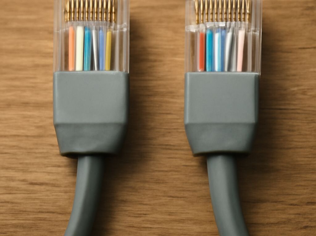
- Hold the plug contacts-up with pin 1 on the left. Slide the conductors into the channels until every conductor reaches the front and the jacket enters beneath the strain-relief tab.
- Inspect the order through the transparent plug. Confirm that the jacket, not just the individual conductors, will be secured by the crimp.
- Use a crimp tool matched to the plug and cable type. Solid-conductor cable and stranded patch cable may require different plugs; do not assume one connector fits both.
- Repeat the selected standard at the other end, then label the cable if the installation contains multiple runs.
Verify pair mapping, continuity, and link speed
- Test the cable with a wire-map tester. Confirm pins 1 through 8 appear in the intended order and that the tester identifies all four pairs correctly.
- Check for opens, shorts, reversals, transposed pairs, and split pairs. Continuity alone is insufficient because a split pair can pass a simple pin-to-pin test.
- Test the permanent cable before connecting the surge protector when practical. Then test through the protector and patch leads to isolate a faulty cable, protector, or connector.
- Connect the equipment and verify the negotiated link speed and duplex. A gigabit link that falls back to 100 Mb/s often indicates a missing pair, split pair, poor termination, damaged patch lead, or incompatible protector.
- For PoE, confirm that the powered device starts correctly and that a suitable tester or switch diagnostic reports the expected PoE class and voltage.
- For critical or high-speed links, use a category certification tester to check insertion loss, return loss, crosstalk, length, and other performance limits rather than relying only on link lights.