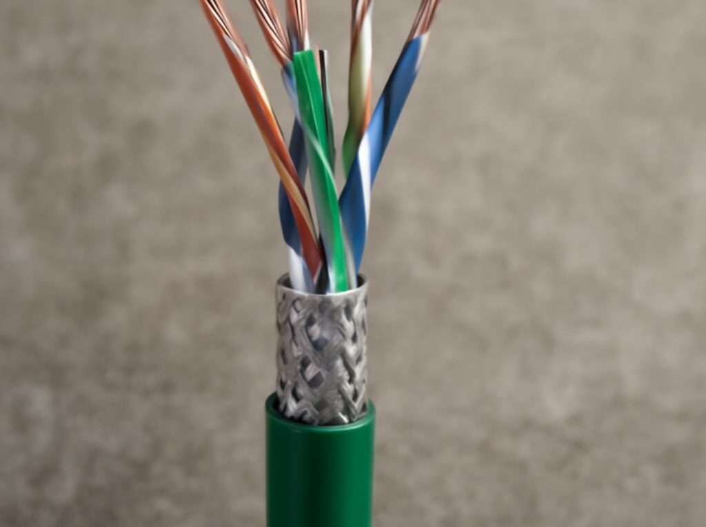
PoE+ Switch Setup with Cat6A Cabling
A PoE+ switch setup works best when the power budget, cable construction, and termination standard all line up. A switch can have plenty of ports and still fail the job if too many endpoints draw near the 25.5W device limit at the same time, or if the cabling cannot carry the signal cleanly over the full run.
Cat6A cabling gives more margin for longer links, higher data rates, and heat from bundled PoE runs, but only if it is terminated correctly and tested as a complete channel. The Ethernet cable color code also matters: the pin order must be consistent end to end, or a link that powers up may still negotiate poorly or flap under load.
Size your PoE+ switch by watts, ports, and reserve capacity
Size a PoE+ switch from the power budget first and the port count second. PoE+ can supply up to 30W per port from the switch, with about 25.5W available to the powered device, so the right question is not just “how many ports are needed?” but “how many watts will all ports draw at once?”
Total PoE budget = peak watts for every powered device + any powered uplinks + 15% to 25% reserve.
A practical example: eight access points at 13W each, six cameras at 8W each, and four phones at 7W each already total 202W. If two uplink ports also power remote devices at 6W each, the subtotal becomes 214W. Add 20% headroom and the target rises to about 257W, which points to a switch with a comfortable power supply, not a marginal one. A 16-port switch with a 120W budget, by contrast, cannot sustain four 25W endpoints even though each port is within the PoE+ limit.
- Check the worst case, not the average. Cameras with IR LEDs, Wi-Fi access points under heavy traffic, and phones with accessories can draw more at peak than they do at idle.
- Account for device class. If LLDP or the device label shows a lower class than the real peak load, size to the higher number.
- Include powered uplinks when they exist. A non-PoE fiber uplink does not consume the budget, but a copper uplink feeding a remote device does.
- Keep reserve capacity. Extra wattage protects the switch from overload and leaves room for future endpoints or seasonal load changes.
Cable length also affects power delivery. Long runs increase resistance, and bundled cables run warmer, so a link that looks fine at the bench can become marginal in the ceiling tray or rack. For high-draw endpoints, shorter pathways, solid copper conductors, and generous power headroom reduce the risk of voltage drop and port shutdown.
Decide when Cat6A is worth it for length, shielding, and bend radius
A Cat6A ethernet cable is worth the extra bulk when the installation needs 10GbE headroom, longer permanent runs, or better tolerance of PoE heat in dense bundles. It is usually the safer choice for ceiling-mounted access points, security cameras, conference rooms, and any drop that may need more bandwidth later. For short desktop patches at 1GbE, Cat6 may be enough; for structured cabling that needs room to grow, Cat6A gives more margin.
Construction matters as much as category. A good Cat6A cable for PoE+ should usually be:
- Solid copper, not CCA. Copper-clad aluminum raises resistance and can reduce PoE voltage at the device.
- Proper gauge for the run. 23 AWG is common in Cat6A and helps keep resistance lower over longer distances.
- Rated for the environment. Plenum, riser, or outdoor jackets should match the installation path.
For data performance, Cat6A is designed to support 10GBASE-T up to 100 meters when the entire channel is installed and terminated correctly. That does not mean every short run needs Cat6A, but it does mean Cat6A is the better selection when the link length is long, the cable path is crowded, or the switch is feeding a high-value device that should not be the first thing to blame.
Keep bend radius generous. Tight bends and crushed cable can pass a continuity test and still fail under load. A useful rule is to avoid bends tighter than about four times the cable diameter, leave slack for service loops, and never cinch cable ties so tightly that they deform the jacket or flatten the pairs. At the rack, ceiling box, and device end, the cable should curve smoothly instead of kinking.
Shielding and grounding deserve the same attention. In electrically noisy spaces, shielded Cat6A can reduce interference, but the shield only helps when the whole channel is built to support it. Use shielded patch panels, jacks, and plugs together, and bond the system to the building grounding path according to the hardware maker’s instructions. A shielded cable landed in unshielded hardware usually loses most of the benefit.
For cleaner office environments, unshielded Cat6A is often simpler and perfectly adequate. The right choice is the one that matches the EMI environment, the cable path, and the termination hardware already in use.
Use the correct Ethernet wire color order for T568A and T568B
The Ethernet cable color code does not change because the link is carrying power. What matters is a consistent pin order. For a standard straight-through run, both ends should use the same scheme. Mixing T568A on one end and T568B on the other creates a crossover cable, which modern switches usually do not need.
For reference, the pin order below assumes the RJ45 plug is held with the contacts facing up and the latch away from view. On a keystone jack, follow the printed pin labels on the part itself.
T568A color order
- Pin 1: white/green
- Pin 2: green
- Pin 3: white/orange
- Pin 4: blue
- Pin 5: white/blue
- Pin 6: orange
- Pin 7: white/brown
- Pin 8: brown
T568B color order
- Pin 1: white/orange
- Pin 2: orange
- Pin 3: white/green
- Pin 4: blue
- Pin 5: white/blue
- Pin 6: green
- Pin 7: white/brown
- Pin 8: brown
The blue pair always stays on pins 4 and 5, and the brown pair stays on pins 7 and 8. Only the orange and green pairs swap between the two standards. That is why the pair twists must stay intact right up to the termination point; splitting a pair across the wrong pins can still pass power but break higher-speed data.
Use the same standard on both ends of the link unless the site already has a defined convention. In many commercial installs, T568B is the default; in some legacy or residential environments, T568A is already established. The key is consistency across the patch panel, wall jack, and patch cord.
For field terminations, match the connector to the cable gauge and conductor type, especially with thicker Cat6A conductors. A jack or plug that is not rated for the cable can nick the conductor, raise resistance, and make PoE performance less stable.
Test the finished link for power, certification, and speed
After termination, test the link in three layers: wire map, PoE delivery, and negotiated data rate. Continuity alone is not enough for a PoE+ switch installation.
- Verify the wire map and certify the channel. Use a cable certifier or qualification tester to confirm pinout, length, insertion loss, NEXT, return loss, and the expected category performance. A simple tone tester can show that the wires are connected, but it cannot prove the link will support the target speed.
- Confirm power delivery under load. Power the actual endpoint or a PoE load tester and check the switch’s reported wattage, class, and any LLDP power negotiation. If a device reboots when its radios, heaters, or IR LEDs turn on, the port may be near its limit or the run may be losing too much voltage.
- Check the negotiated data speed. Make sure the port comes up at the intended rate, such as 1GbE, 2.5GbE, 5GbE, or 10GbE. A fallback to 100Mb/s usually points to a pair split, poor termination, damaged cable, or a connector that was not fully seated.
Testing should reflect real operation, not idle conditions. An access point should be tested while radios are active, and a camera should be tested with its full illumination load if it has one. If the port stays up, the switch reports the expected power draw, and the link negotiates at the correct speed without flapping, the install is ready.