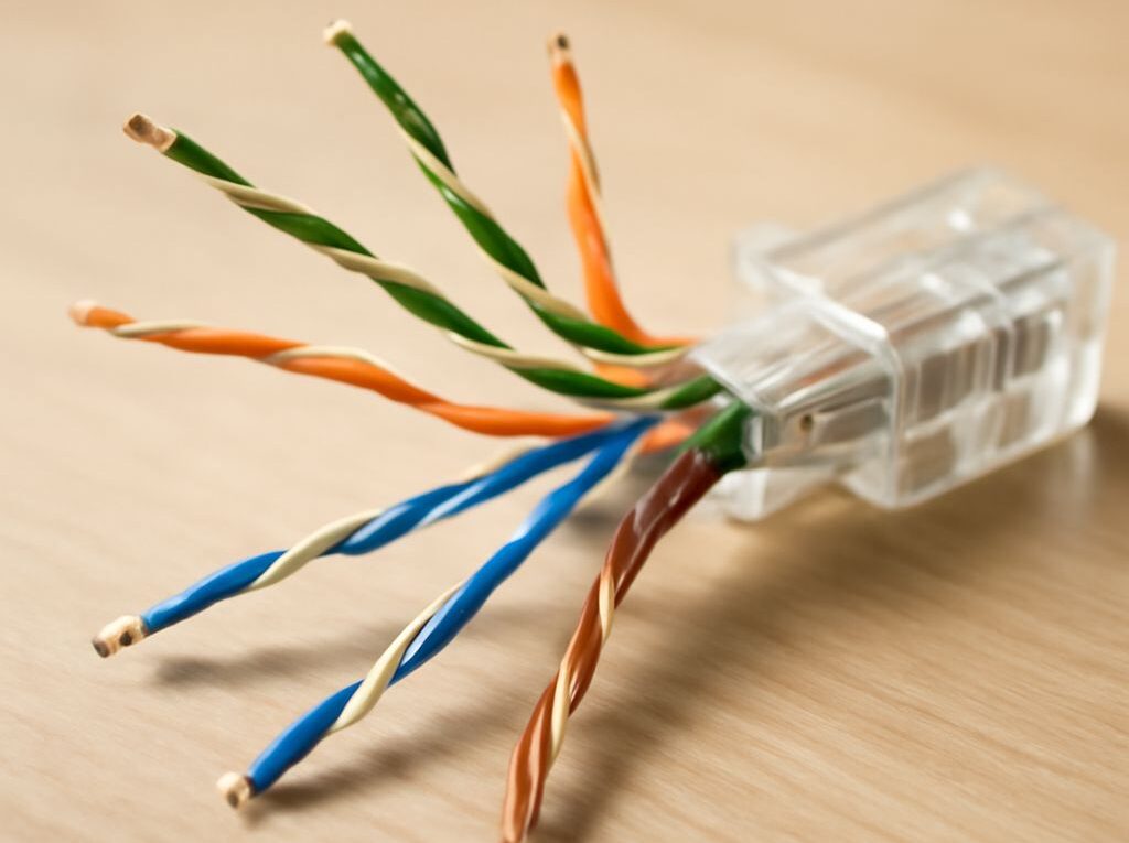
Ethernet Color Code and Pinout: RJ45 Wiring and Coax Links
Correct RJ45 wiring starts with the ethernet pinout: the plug orientation, the conductor order, and whether the cable is a straight-through patch or a crossover. The color code matters because the twisted pairs must land on the right pins for the link speed and equipment type.
Coax is a different medium. Ethernet over coax works only when active devices translate Ethernet to a coax networking standard such as MoCA or G.hn. A passive shape adapter that changes an F connector to RJ45 does not convert the signal by itself.
RJ45 Ethernet pinout and cable-pair roles
Plug orientation and all eight pins
To read an RJ45 plug correctly, hold the plug with the gold contacts facing up and the locking tab away from the viewer. In that view, pin 1 is on the left and pin 8 is on the right. The pin order is fixed; only the wire colors change between T568A and T568B.
- Pin 1 and pin 2 form one twisted pair.
- Pin 3 and pin 6 form the second data pair in 10/100 Ethernet.
- Pin 4 and pin 5 form the third pair.
- Pin 7 and pin 8 form the fourth pair.
On 10/100BASE-T, only pins 1-2 and 3-6 carry data. Pins 4-5 and 7-8 are not used for data in those links, though they may carry power on PoE systems. On Gigabit Ethernet and faster twisted-pair links, all four pairs are active.
Straight-through vs crossover wiring
A straight-through cable keeps the same wiring standard on both ends. Pin 1 connects to pin 1, pin 2 to pin 2, and so on. That is the normal choice for patch cords and most modern installations.
A crossover cable uses T568A on one end and T568B on the other. This swaps the two main data pairs: pins 1-2 on one end land on pins 3-6 on the other end, and vice versa. Older devices sometimes needed a crossover when connecting two like devices directly, such as switch to switch or PC to PC. Most modern ports support auto-MDIX, so the gear detects the crossover and adjusts automatically.
For a new run, the practical rule is simple: use straight-through wiring unless a device manual or an existing plant requires a crossover.
Ethernet color code for T568A and T568B
Color order for each standard
The ethernet color code is the wire order inside the RJ45 connector. Both standards use the same eight positions; T568A and T568B only swap the orange and green pairs.
- T568A
- Pin 1: white/green
- Pin 2: green
- Pin 3: white/orange
- Pin 4: blue
- Pin 5: white/blue
- Pin 6: orange
- Pin 7: white/brown
- Pin 8: brown
- T568B
- Pin 1: white/orange
- Pin 2: orange
- Pin 3: white/green
- Pin 4: blue
- Pin 5: white/blue
- Pin 6: green
- Pin 7: white/brown
- Pin 8: brown
Both standards preserve the blue pair on pins 4-5 and the brown pair on pins 7-8. The difference is the placement of the green and orange pairs. That is why one end wired to A and the other wired to B becomes a crossover.
Which standard to use on both ends
For a straight-through cable, terminate both ends with the same standard. If the site already uses one standard in its patch panels and wall jacks, match it. If the installation is new, consistency matters more than the label: pick T568A or T568B and use it everywhere in that cabling segment.
Common practice varies by region and project. Many commercial patch cords and office installations use T568B, while some structured cabling systems specify T568A. The important part is that every jack, patch panel, and cable in the same run follows the same choice unless a crossover is intentionally needed.
How Ethernet over coax works
Active converters and supported standards
Coax does not carry native twisted-pair Ethernet signaling. To reuse existing coax, the link needs active devices at both ends that convert Ethernet frames into a coax networking protocol and back again. This is where standards such as MoCA and G.hn over coax come in.
MoCA adapters are the most common example in homes and small offices. They connect Ethernet on one side and coax on the other, then create a network bridge over the coax plant. Supported versions include MoCA 1.1, 2.0, and 2.5, with higher versions offering higher physical-layer rates. Real throughput is lower than the headline number because of protocol overhead, signal conditions, and shared use.
That distinction matters because a passive F-type to RJ45 adapter is only a connector change. It does not translate signaling, negotiate speed, or create a network bridge. If the device is not powered and built for coax Ethernet, it is not a universal converter.
Topology, speed sharing, and distance limits
Most coax Ethernet deployments use a single coax domain with splitters, not a direct point-to-point cable like twisted-pair Ethernet. The adapters must see each other on the same coax segment, and the splitters must pass the frequencies used by the chosen standard. Old splitters, loose connectors, and excess attenuation can block the link.
The coax segment is also a shared medium. Every adapter on that coax network shares the available bandwidth, so the usable speed per endpoint drops as more devices move data at the same time. A 2.5 Gbps-class MoCA network does not mean each room gets 2.5 Gbps at once.
Distance limits depend on the standard, coax type, splitter count, and cable condition rather than a single fixed number. Short, clean in-building runs usually work well. Long runs, many splits, damaged coax, or mismatched connectors reduce signal margin and can lower throughput or prevent the link from forming.
For mixed TV and data coax plants, the coax network may also need compatible splitters and, in some layouts, a filter at the entry point to keep the coax network contained. The active adapters still do the real conversion; the coax hardware only carries the signal between them.
Terminate and test the connection
Crimping, punching down, and matching pairs
For twisted-pair Ethernet, terminate the cable with the right connector type for the job. Use a punch-down jack or keystone for solid in-wall cable, and use an RJ45 crimp plug for stranded patch cable unless the plug is specifically rated for solid conductors.
- Keep each twisted pair twisted as close to the termination as practical.
- Do not untwist more wire than needed to seat the conductors.
- Match the same standard on both ends for straight-through wiring.
- Use T568A on one end and T568B on the other only when a crossover is required.
A good termination leaves the conductor order intact right up to the contact points. A poor termination often shows too much untwisting, damaged insulation, or a split pair where wires land in the right pins but the wrong pair grouping. Split pairs can still pass a basic continuity check and still fail under load.
For coax runs, tighten F-type connectors firmly and verify that every splitter, barrel, and wall plate is rated for the coax Ethernet standard in use. A shiny connector that is not compatible with the operating band can still cause an unstable link.
Cable tester, link light, and endpoint checks
Start with a wiremap or continuity tester for RJ45 cable. A correct result shows pin 1 to pin 1, pin 2 to pin 2, through pin 8 to pin 8 on a straight-through cable. For a crossover, the tester should show the expected 1-3 and 2-6 swaps. Look for opens, shorts, split pairs, and reversed conductors.
- RJ45 test: confirm every pin lands where the standard says it should.
- Link light: both Ethernet ports should show link on the negotiated speed.
- IP test: ping the gateway and another device on the far end.
- Throughput test: move a file or run a speed test to confirm usable performance.
On Ethernet-over-coax links, check both adapters. Each unit should show a coax link indicator and an Ethernet link indicator. If the Ethernet side is up but the coax side is down, inspect the coax path, splitter compatibility, and power to the adapters. If the coax side is up but performance is poor, test a shorter path, reduce splitter count, and verify that both adapters support the same standard.
The finished result is a clean wiremap on copper, a stable negotiated link at the expected speed, and on coax-based links, two active endpoints that both report solid coax and Ethernet status.