What Is Structured Cabling? A Copper and Fiber Planning Guide
What is structured cabling? Structured cabling is a standardized building network made from defined spaces, pathways, permanent cable links, patching hardware, outlets, and test records. Instead of treating each cable as an isolated installation, it organizes connectivity from the service entrance and backbone to telecom rooms, work areas, and network equipment.
A maintainable design separates fixed infrastructure from replaceable patch cords and active electronics. Copper commonly serves horizontal connections to desks, access points, phones, and other devices, while fiber provides longer-distance or higher-capacity backbone connections between rooms, floors, and buildings.
What Is Structured Cabling? The Building Blocks of a Maintainable Network
From entrance facilities through equipment and telecom rooms to work areas
The entrance facility is the building’s connection point for service-provider cables and outside-plant pathways. It may contain the demarcation point, splice closures, grounding and bonding equipment, and protection for incoming copper or fiber. From there, backbone cabling connects to the building’s main equipment room.
The equipment room houses core switches, routers, servers, security equipment, and the main distribution hardware. It is normally the central point for backbone terminations and connections to service-provider circuits. Larger buildings may have more than one equipment room, depending on floor area, network architecture, and distance limits.
Telecommunications rooms, also called telecom rooms or intermediate distribution rooms, serve individual floors or zones. They contain racks or cabinets, patch panels, horizontal cable terminations, backbone fiber or copper terminations, and access switches. A telecom room should be positioned so horizontal cable runs remain within their designed distance limits.
The work area is the user or device end of the system. It includes the outlet, faceplate, patch cord, and connected device, such as a computer, wireless access point, camera, or phone. Outlets should be placed where equipment is expected, with additional capacity where future moves are likely.
Backbone, horizontal runs, permanent links, patch panels, and outlets
The backbone, or vertical cabling, connects the entrance facility, equipment room, and telecom rooms. Fiber is common because it supports high bandwidth over long distances and is not affected by electromagnetic interference. Copper backbone links may still be used for specific voice, control, or short-distance applications.
Horizontal runs extend from a patch panel in a telecom room to an outlet or consolidation point in a work area. The fixed cable and its installed connecting hardware form the permanent link. A typical balanced-copper design limits the permanent link to 90 meters. Patch cords at the rack and work area create the channel, commonly limited to 100 meters in total.
Patch panels provide an orderly termination point instead of connecting every permanent cable directly to a switch. Short patch cords then connect panel ports to switches, routers, or other equipment. This arrangement makes moves, additions, troubleshooting, and equipment replacement easier without disturbing cable installed in walls or pathways.
Horizontal Copper: Cat6, Cat6A, and the Cat6e Label
Cat6e vs Cat6A: application, reach, termination, and testing
The cat6e vs cat6a question requires one important distinction: Cat6A is a recognized category, while Cat6e is not a formal cabling category in the main structured-cabling standards. “Cat6e” is a vendor or marketing label that can describe enhanced Cat6, a proprietary construction, or cable marketed as approaching Cat6A performance. Procurement should therefore require the actual standard, performance specifications, and field-test requirements rather than relying on the label.
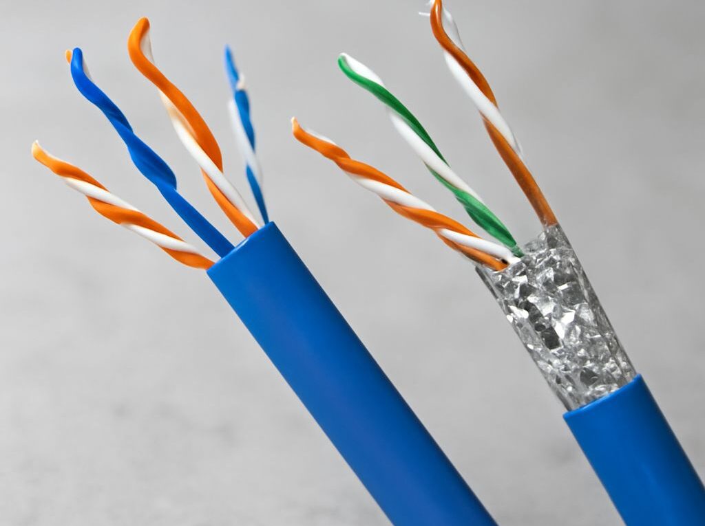
- Cat6: A practical choice for general horizontal cabling and 1-gigabit Ethernet at the full 100-meter channel distance. It can support 10-gigabit Ethernet over shorter distances, but the usable distance depends on cable design, installation conditions, and crosstalk performance. Cat6 uses four balanced twisted pairs and normally terminates on category-rated modular jacks, patch panels, and patch cords.
- Cat6A: Designed for 10-gigabit Ethernet up to the full 100-meter channel distance when the complete link meets the required specifications. It has tighter alien-crosstalk performance requirements and is often larger and less flexible than Cat6. Termination uses Cat6A-rated jacks, patch panels, and patch cords; installation must also account for bend radius, cable separation, pathway fill, and the requirements of any shielded system.
- Marketed Cat6e: Its application and reach cannot be assumed from the name. One product may be tested as Cat6, while another may claim enhanced performance without being a standards-recognized Cat6A system. The manufacturer’s data must identify frequency, insertion loss, crosstalk limits, connector compatibility, and whether the installed link can be certified to a recognized category.
For all three labels, copper horizontal cabling is terminated using insulation-displacement contacts in jacks and patch panels, with modular patch cords connecting the equipment. T568A or T568B pin assignments may be used, but the same scheme should be maintained throughout a link. Mixing schemes can create a crossover connection or a wiring fault.
Testing is performed with a calibrated copper field certifier set for the intended permanent link or channel category. A meaningful result includes wire map, length, insertion loss, return loss, near-end crosstalk, power-sum crosstalk, and other applicable parameters. A cable marked Cat6e should not be accepted simply because it passes a basic continuity test; the installed link must pass the specified recognized test limits.
Choosing category cable for horizontal runs and work areas
Cat6 is often sufficient when the access-switch plan is limited to 1-gigabit connections and the environment has ordinary bandwidth demands. Cat6A is a stronger choice for new buildings expected to support 10-gigabit access, dense wireless access points, high-performance workstations, or long service life without recabling.
The decision should include the complete channel, not just the cable on the reel. Patch panels, outlets, connectors, patch cords, installation workmanship, and pathway conditions all affect performance. Cat6A may require larger pathways and more rack space, while Cat6 may be easier to route in congested spaces. A product sold as Cat6e should be selected only when its documented performance and certification plan meet the design requirement.
Fiber Backbones: Optical Fiber Cable Types and Uses
Single-mode and multimode fiber: reach, application, and cable choice
An optic fiber cable is more commonly specified in technical documents as an optical fiber cable. It carries data as light through glass fibers and is normally used for backbone connections, uplinks, data-center interconnects, and links between buildings. Fiber does not carry electrical power for devices, so a fiber backbone normally connects to copper horizontal cabling at a switch or distribution point.
- Single-mode fiber: Uses a small core and typically operates with 1310-nanometer or 1550-nanometer optics. It supports the longest reach, often kilometers depending on the transceiver and link budget, making it suitable for campus backbones, long building links, and carrier connections. It is usually terminated with precision connectors such as LC or SC, or fusion-spliced to pigtails in a fiber enclosure.
- Multimode fiber: Uses a larger core and is commonly paired with short-wavelength 850-nanometer optics. OM3 and OM4 are common choices for building and data-center backbones. For example, 10-gigabit Ethernet reach is often about 300 meters on OM3 and 400 meters on OM4, although the exact limit depends on the transceiver and application. Multimode generally has lower equipment cost for short links.
Single-mode and multimode cannot be treated as interchangeable at the transceiver. The fiber type, connector format, wavelength, polarity, and optical budget must match at both ends. Single-mode is usually the safer long-reach choice; multimode can be economical where the backbone remains within its supported building distance.
Fiber termination and test methods
Fiber may be terminated with duplex LC or SC connectors for individual strands, or with MPO-style multifiber connectors for high-density parallel-optics systems. Fusion splicing provides a low-loss permanent joint and is common when cable pigtails are installed in patch enclosures. Connector end faces must be inspected and cleaned before testing or connection.
Fiber certification normally uses an optical loss test set, consisting of a light source and power meter, to measure insertion loss and length at the required wavelengths. The test must account for the connector reference method and link polarity. An optical time-domain reflectometer, or OTDR, can locate splices, excessive loss, reflections, and distance to an event. OTDR results complement rather than replace end-to-end insertion-loss testing.
Pathways, Labeling, Testing, and Records
Designing pathways and capacity around permanent links
Pathways include conduit, cable tray, ladder rack, sleeves, raised-floor routes, and overhead support systems. They should be sized for the planned permanent links plus practical spare capacity, with bend radius and pulling tension considered for each cable type. Fiber and copper may require different support, separation, and handling practices.
Routes should limit exposure to electrical interference, avoid sharp edges and excessive compression, and preserve access for future work. Fire-rated wall and floor penetrations require suitable firestopping after cables are installed. Separation from power cabling should follow the applicable electrical and cabling requirements, particularly where copper links run near motors, fluorescent equipment, or other noise sources.
Pathway planning should also reserve space for backbone growth, additional telecom rooms, and changes in work-area density. A crowded tray or conduit can turn a simple expansion into a disruptive construction project.
Testing copper and fiber, then keeping test records
Every installed link should have a unique identifier at both ends. A useful label can identify the building, telecom room, rack, patch panel, port, and outlet—for example, a code that links a rack port to a specific work-area outlet. Labels should remain legible and correspond to the drawings and database.
Closeout records should retain:
- cable type, category, fiber mode, strand count, and manufacturer;
- permanent-link and channel identifiers, endpoint locations, and measured lengths;
- copper certification results for each required performance parameter;
- fiber insertion-loss, polarity, wavelength, and, where required, OTDR results;
- patch-panel, outlet, rack, and backbone termination details; and
- pathway routes, firestop locations, changes made during installation, and test dates.
These records turn structured cabling into an auditable infrastructure system. When a port fails or a new switch is installed, technicians can identify the physical route, confirm the link type, review its original test result, and make changes without guessing which cable serves which location.