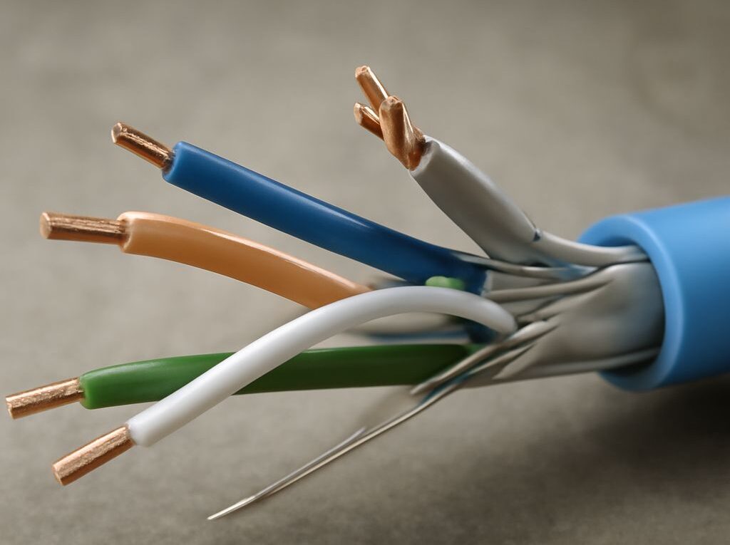
Bulk Ethernet Cable: Cat6A, Cat6e Labels, and RJ45 Pinout
bulk ethernet cable for a permanent network run should normally be solid bare copper, rated for the installation space, and matched to the required category and shielding system. Cat6A is the reliable choice for new 10GbE runs up to the standard 100 m channel limit; a Cat6e label requires closer examination because it is not a formal TIA cabling category.
Before pulling cable, confirm the conductor type, copper material, jacket rating, shield construction, sequential length markings, and manufacturer documentation. After installation, use one wiring standard at both ends, terminate each pair correctly, and test the completed link rather than relying only on a continuity check.
How to Specify Bulk Ethernet Cable for Your Run
Solid versus stranded conductors, copper versus CCA
Solid copper cable uses one solid conductor for each wire. It has predictable electrical performance over permanent horizontal runs and is designed for termination on keystone jacks, patch panels, and compatible field plugs. Most bulk cable intended to be pulled through walls, ceilings, or conduit should be solid conductor cable.
Stranded copper cable uses several smaller strands in each conductor. It is more flexible and better suited to short patch cords that move repeatedly between a switch, patch panel, computer, access point, or other device. Stranded cable generally has greater attenuation than equivalent solid cable and may not seat correctly in insulation-displacement terminals designed for solid conductors. A bulk spool advertised for flexible patching should not automatically be used for permanent in-wall cabling.
Check that the conductors are bare copper or another material explicitly identified as compliant with the applicable cabling standard. Copper-clad aluminum (CCA) has an aluminum core with a thin copper coating. It is not equivalent to compliant solid copper: its electrical resistance, termination behavior, mechanical properties, and power-delivery performance differ. CCA can create problems with PoE voltage drop, connector heating, and category performance, particularly over longer runs. A low price should not outweigh the specification and safety requirements of the installation.
Jacket ratings, shielding, length markings, and application support
Choose the jacket for the route, not simply the cable category. Common ratings include:
- CMP, or plenum: intended for air-handling spaces where building codes require a low-smoke, flame-resistant jacket.
- CMR, or riser: intended for vertical runs and general in-wall use where a riser rating is accepted.
- CM or general-purpose: suitable only where local code permits it; it is not a substitute for CMP in a plenum.
- LSZH: a low-smoke, zero-halogen construction used where the project specification requires it, especially in some commercial or international environments.
- Outdoor or direct-burial: built for moisture, sunlight, temperature changes, or burial conditions. Indoor-rated cable should not be placed outdoors merely because it is inside conduit.
Shielding is specified separately from category. U/UTP cable has no overall shield and is suitable for most ordinary office and residential routes. F/UTP adds an overall foil, while S/FTP and related constructions use combinations of braid and pair foils. Shielded cable can help in areas with substantial electromagnetic interference, such as near motors, fluorescent equipment, or high-voltage infrastructure. It works as a system, however: shielded jacks, patch panels, plugs, and a properly bonded grounding path are also required. Installing a shielded cable with unshielded components does not provide a complete shielded channel.
Look for sequential footage or meter markings printed along the jacket. These markings help estimate the installed length, identify the cable used at each end, and calculate remaining stock. The spool length is not the same as the finished channel length: allow for routing, service loops, patch-panel slack, and patch cords. Confirm the cable’s outside diameter, minimum bend radius, pulling tension, operating temperature, and PoE support in the manufacturer’s datasheet. Those details determine whether it fits the pathway and the intended application.
Cat6A vs Cat6e: Which Label Can You Trust?
For a cat6a vs cat6e decision, Cat6A is the clearly defined option. Category 6A is recognized by the TIA cabling standard and is specified to support 10GBASE-T over a channel up to 100 m when the permanent link, connectors, patch cords, installation practices, and testing all meet the required limits. Cat6A commonly has a 500 MHz rating and may be larger or less flexible than Cat6 because of its separator, conductor size, or shielding.
Cat6e is not a formal TIA category. Some sellers use the label to describe an enhanced version of Cat6, but there is no single industry-wide Cat6e performance definition. One product may claim a higher frequency, while another may use the term primarily for marketing. The label alone does not establish 10GbE distance, crosstalk performance, conductor quality, or compliance.
Cat6 is a formal category commonly rated to 250 MHz. It supports 1GbE over standard channel distances and can support some 10GbE installations over shorter distances, depending on the cable, channel design, alien crosstalk, and test results. It may be a sensible choice for existing networks, shorter runs, or applications that do not require 10GbE. Cat6A is generally the safer selection for new infrastructure where 10GbE, future capacity, or a full 100 m channel is important.
When reviewing a cable marketed as Cat6e, request the same evidence expected for a standards-based product:
- A stated TIA or ISO category and the applicable test frequency.
- Conductor material, gauge, impedance, and electrical performance data.
- Supported channel length and the specific connectors used for testing.
- PoE support, outside diameter, bend radius, and jacket certification.
- A manufacturer’s permanent-link or channel test documentation, not only a speed claim.
If the documentation does not clearly identify a recognized category, choose certified Cat6 or Cat6A instead. A Cat6e marking should never be treated as automatically equivalent to Cat6A.
Ethernet Cable Pinout: T568A and T568B Wiring Order
An ethernet cable pinout identifies which colored conductor occupies each of the eight contacts in an RJ45-style 8P8C plug or jack. T568A and T568B use the same four twisted pairs but place the green and orange pairs in different positions. The important rule is consistency: use the same standard at both ends for a normal straight-through cable.
T568A: pins 1–8
With the connector held in the same orientation for both ends, place the conductors in this order from pin 1 through pin 8:
- Pin 1: white/green
- Pin 2: green
- Pin 3: white/orange
- Pin 4: blue
- Pin 5: white/blue
- Pin 6: orange
- Pin 7: white/brown
- Pin 8: brown
T568B: pins 1–8
T568B is widely used in commercial patching and is electrically equivalent to T568A when the same standard is used at both ends. Its pin order is:
- Pin 1: white/orange
- Pin 2: orange
- Pin 3: white/green
- Pin 4: blue
- Pin 5: white/blue
- Pin 6: green
- Pin 7: white/brown
- Pin 8: brown
Do not identify conductors by color alone without checking the stripe. The white/green and white/orange wires must remain paired with their matching solid-color wires. If one end is T568A and the other is T568B, the cable is a crossover arrangement. Modern network equipment often handles this automatically, but a structured-cabling installation should normally follow the site’s selected standard at every outlet and patch-panel position.
Terminate and Certify the Installed Link
Prepare, terminate, test, and certify the completed cable run
- Plan the route. Keep data cable separated from power wiring as required by local code and the installation design. Avoid sharp bends, crushing, staples that deform the jacket, excessive pulling force, and long parallel runs beside sources of electrical interference. Maintain the manufacturer’s bend-radius requirement, commonly at least four times the cable’s outside diameter for fixed cable.
- Choose compatible hardware. Match the jack, patch panel, or field plug to the cable category, conductor type, conductor gauge, outside diameter, and shielding. Solid bulk cable usually belongs on punchdown hardware. Use an RJ45 plug only when it is specifically rated for that cable construction.
- Strip carefully. Remove only enough jacket to place the pairs into the termination. Preserve the pair twists as close to the contacts as practical; excessive untwisting increases crosstalk and can cause a high-category link to fail. For shielded cable, keep the foil or braid and drain connection intact according to the hardware instructions.
- Arrange the conductors. Select T568A or T568B, then place all eight wires in the correct order. Check the sequence twice before seating it. The jacket should enter the connector or jack far enough for the strain relief to grip it, while the individual contacts reach their assigned terminals.
- Terminate both ends. Use the same wiring standard for a straight-through permanent link. Seat each conductor fully and ensure no pair is split. A shielded connection also needs continuity through the shielded components and a proper bonding path.
- Perform a wiremap test. A basic tester can identify opens, shorts, reversed pairs, crossed pairs, and some split-pair errors. A light or continuity result alone does not prove that the cable meets Cat6 or Cat6A performance.
- Certify the link when required. Use a calibrated certifier set for the installed category and the correct permanent-link or channel model. Certification evaluates measurements such as insertion loss, return loss, near-end crosstalk, length, resistance, and related limits. Cat6A certification requires Cat6A-rated test equipment and compatible remote hardware.
A passing link has the correct pin map, intact pair relationships, secure strain relief, and test results within the selected category limits. If it fails, inspect first for a split pair, excessive untwist, an incompatible plug, poorly seated conductors, a crushed section, excessive length, or an incomplete shield bond. Correct the termination or damaged section and test again before placing the run into service.