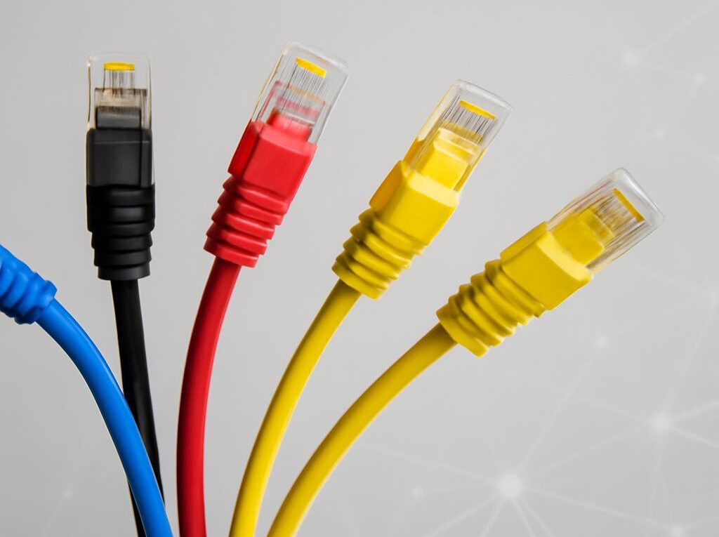
Coax to RJ45: Convert Coax and Choose Cat5e or Cat6
A coax to RJ45 upgrade requires an active Ethernet-over-coax adapter system, usually based on MoCA. One adapter connects to the router or switch with Ethernet, and a second adapter connects to the remote device through the existing coax. A passive plug cannot translate coaxial RF signaling into Ethernet signaling.
After the coax segment reaches the remote adapter, the connection becomes ordinary copper Ethernet at the RJ45 port. The cable choice after that handoff is separate from the coax conversion: Cat5e is the practical minimum for new gigabit segments, while Cat6 provides more crosstalk margin and a better path toward higher speeds. The “Cat6e” label needs careful scrutiny because it is not a formal TIA cable category.
How coax to RJ45 conversion reaches Ethernet
An active coax adapter pair works as a bridge between two media types. On the router side, the adapter receives Ethernet through its RJ45 port and modulates that traffic onto the coaxial cable. At the far end, the second adapter demodulates the signal and presents Ethernet again through another RJ45 port.
The usual arrangement is:
- Router or switch to the first adapter with an Ethernet patch cable.
- First adapter through a coax wall outlet, splitter, or dedicated coax run.
- Remote coax outlet to the second adapter.
- Second adapter to a computer, access point, game console, switch, or other Ethernet device.
The remote adapter is an Ethernet handoff, not merely a connector change. Its RJ45 port negotiates a normal Ethernet link, such as 1Gbps or 2.5Gbps, according to the adapter, connected cable, and device. A Cat6 patch cable cannot make a low-rate coax adapter deliver a faster connection than the adapter supports.
Coax topology and splitters
MoCA-based systems can operate over a direct coax run or a shared in-home coax topology. With a direct run, the path is relatively simple. With multiple rooms, the coax network may contain splitters that let several adapters communicate over the same RF distribution system. The adapters then share the available coax bandwidth rather than receiving a completely separate full-speed link.
Every splitter in the path matters. A splitter must cover the frequency range used by the adapter, commonly including MoCA frequencies, and it must have acceptable insertion loss. Older television-only splitters may attenuate or block the adapter signal. Cascaded splitters add more loss, and an amplifier designed only for television or cable-modem signals may prevent the adapters from communicating. A MoCA-compatible amplifier or appropriately designed distribution system may be required.
Unused splitter ports should be terminated as specified by the splitter manufacturer. A disconnected or poorly terminated branch can create signal reflections and reduce reliability. RG6 coax is generally preferred for longer or higher-frequency runs because it usually has lower loss than older RG59, although the actual cable condition, connectors, and topology remain decisive.
Frequency coexistence and power
Coax conversion uses RF frequencies that may coexist with television and some cable-internet services, but compatibility depends on the adapter and the service equipment. A point-of-entry MoCA filter can keep the in-home MoCA signal from escaping onto an outside plant and can improve isolation. The filter must be installed in the correct location and must not disrupt the required cable or television service.
Satellite systems, legacy cable equipment, active amplifiers, and nonstandard splitters can use overlapping or unsuitable frequency ranges. The adapter documentation should identify supported coexistence modes and required filters. A coax path that carries television successfully is not automatically suitable for Ethernet-over-coax.
Each active adapter normally needs local AC power. The coax cable generally does not power the adapter, so a remote room needs both a coax outlet and a power outlet. Power over Ethernet can be supplied after the remote adapter if the adapter or an attached PoE switch supports it; that does not power the coax adapter itself.
Shared throughput and the Ethernet handoff
Advertised coax speeds are commonly physical-layer rates. Actual application throughput is lower because of protocol overhead, RF conditions, adapter processing, and traffic shared among nodes. Multiple remote adapters can also compete for the same coax capacity. A single remote link may perform well while simultaneous transfers expose the shared-medium limit.
For testing, connect a wired device to each adapter rather than judging the system through Wi-Fi. Check the negotiated Ethernet rate at both RJ45 ports, then use a local throughput tool such as iperf3 between wired endpoints. If the adapter diagnostic reports a strong coax link but the Ethernet port negotiates at 100Mbps, inspect the patch cable, connectors, and device port. If individual links are fast but simultaneous room-to-room transfers slow down, shared coax capacity is the likely constraint.
Difference between Cat5 and Cat5e: speed, distance, and certification
The difference between Cat5 and Cat5e is mainly the performance standard and the applications each cable can support reliably. Legacy Cat5 was designed around 100MHz signaling and is commonly associated with 100BASE-TX Fast Ethernet at up to 100 meters. Cat5e adds tighter performance requirements and is the established choice for 1000BASE-T gigabit Ethernet over a 100-meter channel.
The 100-meter figure includes the complete channel: typically up to 90 meters of permanent cable plus up to 10 meters of patch cords. It assumes compliant cable, connectors, installation practices, and testing. Excessive untwisting, poor terminations, tight bends, cable damage, or electromagnetic interference can reduce the usable distance for either category.
- Cat5: A legacy category suitable for older 100Mbps installations when its condition and test results are acceptable. It may sometimes carry gigabit Ethernet, but that should not be assumed for a new design.
- Cat5e: The normal baseline for new gigabit cabling. It has improved crosstalk and transmission requirements that support 1000BASE-T across the standard channel distance.
Both types use four balanced twisted pairs in a 100-ohm cable system. Cat5e is not defined simply by a thicker jacket or a higher printed frequency. Its performance depends on pair balance, insertion loss, return loss, and near-end and far-end crosstalk limits. A cable can look well made and still fail certification if its geometry or termination is poor.
Construction, termination, and certification
Cat5e may be unshielded twisted pair or shielded cable, and conductor size can vary within the permitted design. The category marking, solid-copper construction, connector compatibility, and test documentation are more useful than appearance alone. Copper-clad aluminum cable should not be treated as an equivalent substitute for standards-compliant solid copper horizontal cable, especially for permanent runs or Power over Ethernet.
Termination is performed on compatible 8P8C modular jacks and plugs commonly called RJ45. Use one wiring scheme, normally T568A or T568B, consistently at both ends of a patch or permanent link. The twists should be preserved as close as possible to the termination, and the cable should not be crushed or bent beyond its specified radius.
For a reused cable, a link light only proves that some signaling is present. It does not prove a compliant gigabit channel. A cable certifier can test wire map, length, insertion loss, return loss, and crosstalk. Certification is especially valuable when a Cat5 run is being considered for gigabit service or when a coax adapter’s Ethernet handoff repeatedly falls back to 100Mbps.
Difference between Cat6 and Cat6e: crosstalk, construction, and standards
The difference between Cat6 and Cat6e is that Cat6 is a formal standardized category, while Cat6e is generally a marketing designation. Cat6 is specified for higher performance than Cat5e, including a nominal 250MHz bandwidth and stricter crosstalk requirements. Cat6 supports 1000BASE-T to 100 meters and can support 10GBASE-T over shorter distances, often up to about 55 meters depending on installation quality, cable bundling, and alien-crosstalk conditions.
Cat6 commonly uses tighter pair twists, larger conductors, improved separators, or other geometry that keeps pairs farther apart. A plastic spline is common but not mandatory. These construction features reduce coupling between pairs; they do not independently establish the category. The completed cable, connectors, installation, and test results must meet the relevant performance limits.
Cat6 is not automatically a 100-meter 10-gigabit solution. For a planned 10GBASE-T link across the full 100-meter channel, Cat6A is the conventional standardized choice. Cat6 can still be useful for new gigabit runs, shorter 10Gbps links, and installations where additional crosstalk margin is worth the added cable size and termination care.
What the Cat6e label means
Cat6e is not a formal ANSI/TIA category equivalent to Cat5e, Cat6, or Cat6A. Manufacturers may use the label for enhanced Cat6 products with their own frequency or crosstalk claims, but the label has no single universal performance definition. One Cat6e product may not provide the same tested capability as another.
When evaluating a cable marked Cat6e, look for a precise standards reference, the supported application and channel length, conductor construction, connector requirements, and a certification report. A claim such as 350MHz or 500MHz does not by itself guarantee 10Gbps operation at 100 meters. If the design requires predictable 10Gbps performance, specify Cat6A rather than relying on the Cat6e name.
Cat6 termination also requires attention to pair geometry. Keep each pair twisted to the point required by the connector, use Cat6-rated jacks and patch panels, respect the larger cable’s bend radius, and avoid excessive bundling. A Cat6 permanent link terminated with unsuitable Cat5e components can lose the intended performance. Shielded Cat6 or Cat6A requires a compatible grounding and bonding plan; adding shielded plugs to an otherwise ungrounded system does not automatically improve it.
Choose and test the combined path: coax first, cable second
Choose the two parts of the upgrade separately. First establish whether the coax network can carry the required traffic. Then select the Ethernet cable at each adapter handoff and on any new twisted-pair run.
- Map the coax path. Identify the source outlet, destination outlet, splitters, amplifiers, filters, and unused branches. Record whether television or cable-internet service shares the cable. A direct run with few connections is easier to validate than a long chain of unknown splitters.
- Verify adapter requirements. Confirm the adapter technology, supported coax frequencies, Ethernet port rate, required filters, and power arrangement. Use a matched or documented-compatible pair. If several rooms will be connected, check the expected aggregate throughput rather than adding the advertised point-to-point rates.
- Install the coax bridge. Connect the first adapter to the router or switch and the remote adapter to the destination device. Ensure both adapters have power. Check coax synchronization and Ethernet link indicators before changing the wiring.
- Check the Ethernet handoff. Use a standards-compliant Cat5e patch cable for a normal gigabit connection. Use Cat6 when a new run needs more crosstalk margin or may support shorter 10Gbps links. The cable category cannot correct a weak coax signal or increase the adapter’s maximum port speed.
- Test one link and then the shared network. Confirm negotiated Ethernet rates, run a wired local throughput test, and repeat with simultaneous transfers from multiple remote adapters. Compare results with the adapter’s coax diagnostics. Low coax rates point toward topology, splitter loss, interference, or distance; low RJ45 rates point toward the patch cable, termination, or endpoint.
- Certify permanent twisted-pair runs. For new or retained Ethernet cable, test the complete channel. If the installation must support 10Gbps at 100 meters, use Cat6A and certify it for that application. If it needs gigabit service only, correctly installed Cat5e is normally sufficient.
This separation prevents a common upgrade error: replacing the short RJ45 patch cable with Cat6 while leaving an unsuitable splitter or damaged coax path unresolved. The coax system determines how traffic reaches the room; the category-rated twisted pair determines how reliably Ethernet travels from the adapter to the local device.