Ethernet Wall Jack Installation: Plan, Wire, and Test at Home
An Ethernet wall jack provides a fixed connection between a room and a central network panel. The reliable way to install one is to design the permanent link first: decide where each endpoint belongs, route one cable from the panel to each jack, and choose patch cords only after the in-wall run is complete.
Good home ethernet wiring uses solid twisted-pair cable, consistent terminations, labeled runs, and tests at both ends. For standard copper Ethernet, the permanent link should be no longer than 90 m (295 ft), while the complete channel—including patch cords—should remain within 100 m (328 ft).
Plan an Ethernet wall jack layout from the central panel
Choose the central location and map every endpoint
Choose a central, accessible location for the patch panel, switch, router connection, and cable slack. A structured wiring enclosure, utility room, basement, or network closet can work if it has suitable ventilation, power, and room for future service. The panel should not be sealed behind finished construction where each cable cannot be reached and identified.
List each intended endpoint before drilling or pulling cable. Typical locations include a home office, television, access point, security camera, printer, and gaming or media area. One cable per jack is the normal starting point; two cables to a desk or media location can avoid a later rework. Each run should have a direct route from the central panel to the room jack rather than passing through another jack.
Measure the likely pathway, not just the straight-line distance. Add vertical travel, entry into the wall box, routing around framing, and service slack at both ends. A route that appears to be 60 m on a floor plan can become substantially longer after it follows joists, rises between floors, and enters the panel.
Use a star topology and leave service slack
Home Ethernet is normally installed in a star topology: every room jack has its own cable returning to the central panel. This arrangement makes faults easier to isolate and allows each port to connect to a switch independently. Do not wire jacks in a chain or rely on one jack to feed the next; ordinary Ethernet access switches belong at the panel or at a deliberate endpoint.
Leave a manageable service loop at the panel and enough slack at the wall box to remove the jack and reterminate it later. Avoid tightly coiling excess cable, crushing it behind the plate, or using staples that deform the jacket. Secure cable with low-pressure supports designed for communications cable.
Place endpoints before choosing patch cords
Install the wall box where furniture, appliances, and the finished floor will not obstruct the jack. Keep the jack away from likely water exposure and from locations where a cable will be sharply bent immediately after it exits. The panel location and in-wall route determine the permanent link; patch cords should then be selected to bridge the final short distances to the switch and device.
Use solid horizontal cable for the permanent link and stranded patch cords for flexible connections. A short patch cord is preferable to extending an in-wall cable across a room. If a device needs a different connector or a longer lead, account for that cord within the total channel length.
Check maximum ethernet cable length and pathway limits
Choose Cat 6 or Cat 6A for the planned speed
Cat 5e can support common 1 Gb/s installations, but Cat 6 is a practical choice for new residential runs because it provides more performance margin and supports 10 Gb/s over shorter distances when the installation and equipment allow it. Cat 6A is the stronger choice where 10 Gb/s is required across the full distance, where higher alien-crosstalk performance matters, or where the cable will be difficult to replace.
Use cable with solid copper conductors and a jacket rating appropriate to the route. Avoid copper-clad aluminum cable because its electrical performance and mechanical reliability are unsuitable for a permanent Ethernet link. Keep the cable category, connector rating, and patch-panel hardware reasonably matched; a higher-category cable does not make a lower-category jack perform at the higher category.
Use the 90 m permanent-link and 100 m channel limits
The 90 m (295 ft) limit applies to the permanent link from the panel termination to the wall-jack termination. The 100 m (328 ft) channel limit includes both ends of that link plus patch cords and other connecting hardware. A useful planning allowance is therefore:
- Permanent link: up to 90 m (295 ft) of fixed horizontal cable.
- Channel: up to 100 m (328 ft) total, including patch cords.
- Practical design: keep long runs below the limit when possible so routing changes and service slack do not consume the entire allowance.
For example, a 78 m permanent link with a 5 m panel patch cord and a 3 m device patch cord creates an 86 m channel. A 90 m permanent link with 10 m of combined patch cords would exceed the 100 m channel limit. Beyond the standard copper distance, a switch, fiber link, or another active network design is needed rather than simply adding passive couplers.
Route away from power, respect bend limits, and firestop penetrations
Keep communications cable separated from mains wiring to reduce electrical interference and to follow applicable electrical rules. Do not place Ethernet cable in the same conduit or raceway as power conductors unless the pathway and local requirements specifically permit it. When a parallel route is unavoidable, increase separation; when cables cross, crossing near 90 degrees generally reduces coupling.
Follow the cable manufacturer’s minimum bend radius, especially for Cat 6A and shielded cable. Do not kink, sharply fold, pull excessively, or compress the cable with tight ties. Keep twists intact as close as possible to each termination, and avoid untwisting more conductor length than the jack or panel instructions require.
Seal or firestop holes through fire-rated walls, floors, and ceilings with an approved material that maintains the assembly’s rating. Seal ordinary penetrations as required to limit drafts, smoke, pests, and sound transfer. A cable pass-through should not leave an unprotected opening between floors or between fire-separated spaces.
Terminate home ethernet wiring at the panel and wall jack
Punch down T568A or T568B consistently
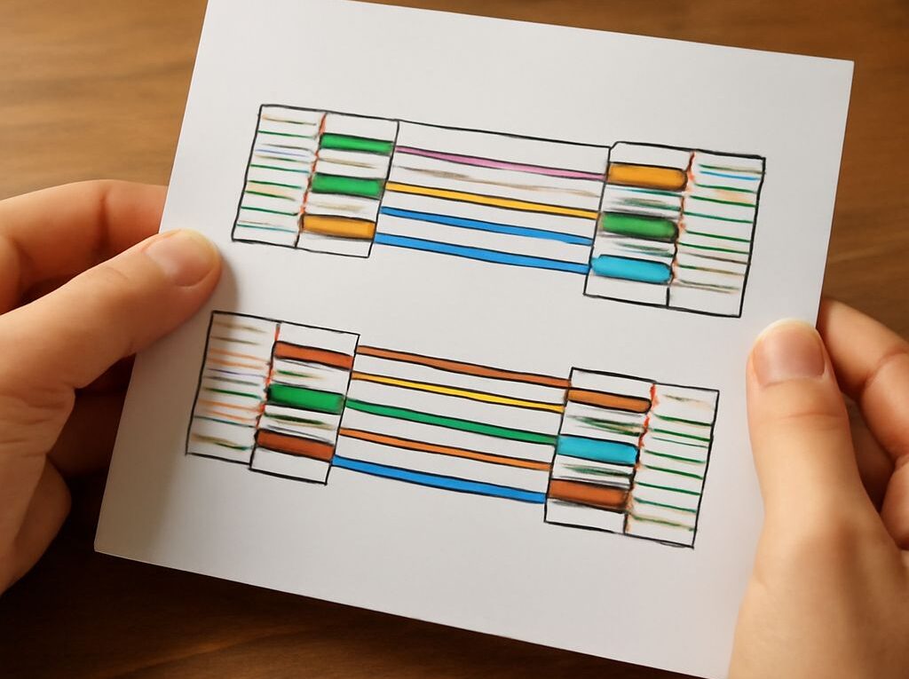
T568A and T568B use the same four twisted pairs but place the green and orange pairs differently. Either scheme works for a normal straight-through Ethernet channel. The important rule is to use the same scheme at both ends of every run unless a specific crossover design is required.
- T568A pin order, 1 through 8: white/green, green, white/orange, blue, white/blue, orange, white/brown, brown.
- T568B pin order, 1 through 8: white/orange, orange, white/green, blue, white/blue, green, white/brown, brown.
Follow the color diagram printed on the chosen patch panel and keystone jack. Place each conductor in its matching slot, preserve the pair twist up to the termination, and seat the conductor with a compatible punch-down tool. Trim the excess conductor cleanly. Do not strip back more jacket than necessary, and do not force a cable into a jack that is not rated for its conductor size or category.
Work through a complete room-to-panel termination example
Assume a home office is 42 m (138 ft) from the central panel by the actual pathway. The installer chooses Cat 6 solid-copper cable, a Cat 6 patch-panel port, and a Cat 6 keystone jack. The planned permanent link is 42 m, leaving substantial room below the 90 m limit for the route and service loops.
- Mark the office jack as OFFICE-1 and mark the matching panel port with the same identifier.
- Pull one continuous cable from the panel to the office box. Protect it from sharp edges, support it without crushing the jacket, and leave service slack at both ends.
- At the panel, remove only the necessary jacket, place the pairs into the panel’s T568B guide, and punch down all eight conductors.
- At the office, terminate the other end on the keystone’s T568B guide. Mount the keystone in the wall plate and secure the plate to the box.
- Connect a short patch cord from panel port OFFICE-1 to a switch port, then connect another patch cord from the office jack to the computer or access point.
If T568A was selected for the project, use its printed A layout at both the panel and the office jack instead. A single A end and B end can produce a crossover arrangement; modern equipment may correct it automatically, but consistent terminations are easier to document and troubleshoot.
Label, patch, and test every run
Use wire-map testing and verify link negotiation
Test the installed cable before closing the work area and again after patching it into active equipment. A basic wire-map tester can identify opens, shorts, reversed pairs, split pairs, and misordered conductors. Test the permanent link with the patch cords removed when the tester supports that method, then test the complete channel with the intended cords connected.
A correct wire map is necessary but does not prove that the link will operate at its intended speed. Connect compatible network equipment and check link negotiation at the switch and endpoint. Confirm the negotiated speed and duplex, such as 1 Gb/s full duplex or 2.5 Gb/s full duplex. A connection that falls back to 100 Mb/s can indicate a damaged pair, poor termination, unsuitable hardware, or excessive length even when a basic continuity test passes.
Failure cues include an intermittent link when the cable is moved, a wire-map error on only one end, a link that negotiates below the expected rate, or a tester result that changes after the jack is reinstalled. Recheck the color code, pair twist, conductor seating, cable damage, patch cords, and switch-port settings before replacing the entire run.
Create labels and a finished-run record
Use a durable, readable identifier at the wall jack, behind the faceplate if space permits, and at the matching panel port. Labels such as OFFICE-1, LIVING-TV-1, and UPSTAIRS-AP-1 are more useful than numbers with no room reference. Keep the label on the cable as well as on the hardware where the installation allows.
Record each finished run in a network log containing:
- Run ID and endpoint location.
- Panel port and wall-jack port.
- Cable category, jacket type, and approximate installed length.
- Termination scheme: T568A or T568B.
- Pathway notes, penetrations, and any firestopping performed.
- Wire-map result, test date, and negotiated link speed.
- Patch-panel and switch-port assignments.
For the office example, the record would state: OFFICE-1, panel port 07 to the office keystone, Cat 6 solid copper, approximately 42 m, T568B at both ends, wire map passed, and 1 Gb/s full-duplex negotiation confirmed. This record makes the next repair, equipment change, or room expansion substantially faster.