How to make an Ethernet cable for an Ethernet-over-coax link
To learn how to make an Ethernet cable for an Ethernet-over-coax system, build and test each RJ45 lead before connecting any coax equipment. Use solid-copper Cat5e or Cat6 cable, terminate both ends with the same wiring standard, and confirm the wire map with a cable tester.
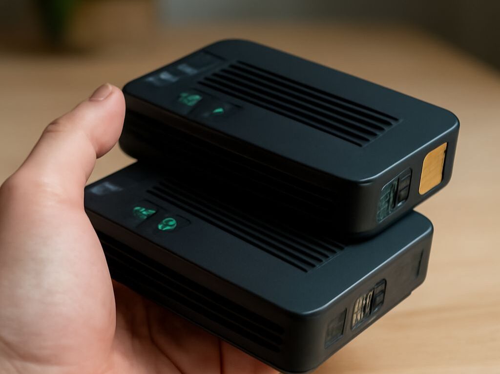
An internet over coax link requires two compatible, powered active adapters, such as a matched MoCA pair or a matched G.hn pair. A passive RJ45-to-coax shape adapter cannot convert Ethernet signals for transmission over coax.
How to make an Ethernet cable: choose the cable, plugs, tools, and coax adapters
Choose solid-copper Cat5e or Cat6 cable, plugs, and tools
- Use solid-copper Cat5e or Cat6 twisted-pair cable. Avoid copper-clad aluminium cable, which has higher resistance and is less suitable for permanent runs.
- Choose RJ45 plugs designed for the cable type and conductor size. Solid-conductor plugs and stranded-conductor plugs do not always use the same contact design.
- Prepare a cable stripper, flush cutter, compatible crimping tool, and an Ethernet cable tester with a remote unit.
- Use a boot or strain-relief sleeve if the installation needs additional protection, but confirm that it fits the selected plug.
For a permanent installation, keep the horizontal cable run within 90 metres, with patch leads bringing the total channel length to no more than about 100 metres. Measure enough cable to reach the device without tension, but avoid tightly coiling excess cable near power supplies or coax equipment.
Select two matched active adapters using the same coax standard, such as MoCA or G.hn
Choose a pair of adapters that use the same coax networking standard and are rated for the intended coax wiring. A MoCA adapter must connect to another compatible MoCA adapter; a G.hn coax adapter must connect to a compatible G.hn unit. Different standards are not automatically interoperable.
Each adapter normally has an Ethernet port, a coax port, a power input, and status lights. The Ethernet lead connects a router, switch, computer, access point, or other network device to the adapter’s LAN port. The coax port connects to the building’s coaxial cable system.
Use matched active coax adapters—not a passive RJ45-to-coax shape adapter
The adapters contain the electronics that modulate Ethernet traffic onto the coax frequency range and recover it at the far end. A passive plug that merely changes an RJ45-shaped connector to a coax connector has no such circuitry and will not create an Ethernet-over-coax link.
Arrange the RJ45 colour code for T568A or T568B
Orient the RJ45 plug and count the pins from left to right
Hold the RJ45 plug with the gold contacts facing up and the retaining latch facing away or down. Viewed from the contact side, pin 1 is on the left and pin 8 is on the right. The RJ45 colour code describes the conductor order entering those eight contacts.
Striped conductors are normally white with a coloured stripe, such as white/green. Keep each twisted pair identifiable while arranging the conductors. The blue pair occupies the centre positions in both standards.
T568A pin order
- Pin 1: white/green
- Pin 2: green
- Pin 3: white/orange
- Pin 4: blue
- Pin 5: white/blue
- Pin 6: orange
- Pin 7: white/brown
- Pin 8: brown
T568B pin order
- Pin 1: white/orange
- Pin 2: orange
- Pin 3: white/green
- Pin 4: blue
- Pin 5: white/blue
- Pin 6: green
- Pin 7: white/brown
- Pin 8: brown
Use the same wiring standard at both ends of a straight-through lead
Use T568A at both ends or T568B at both ends for a normal straight-through Ethernet lead. Do not mix the standards accidentally. An A-to-B lead is a crossover cable; many modern network ports can compensate for one, but a consistent straight-through lead is the reliable choice for coax adapters and general network installation.
Crimp and test the Ethernet leads before attaching coax adapters
Prepare the cable by measuring, stripping, preserving pair twists, aligning, and trimming
- Cut the cable to the required length with a square end.
- Slide on the boot, if one is being used.
- Remove roughly 25 to 40 millimetres of the outer jacket without nicking the insulated conductors.
- Untwist only the amount needed to arrange the wires. Keep the twists as close as practical to the plug; no more than about 13 millimetres of untwisted conductor is a useful maximum for Cat5e and Cat6 terminations.
- Separate the four pairs and place the conductors in the selected T568A or T568B order.
- Flatten the ordered conductors between the fingers, check the order again, and trim their ends square so they are the same length.
Crimp each plug so the outer jacket is captured inside the plug
Push the ordered conductors into the plug until every conductor reaches the front and remains in its own channel. The outer jacket must extend inside the rear of the plug, beyond the point where the strain-relief tab will press down. The contacts should pierce the individual insulation, while the crimp tab should hold the jacket rather than only the eight loose wires.
Check the order through the transparent plug before crimping. Insert the plug fully into the correct die of the crimping tool and close the tool completely in one firm action. After crimping, inspect the contact blades, the jacket capture, and the latch. Repeat the termination if a conductor is short of the front, the jacket is outside the plug, or the contacts are uneven.
Run a wire-map check for opens, shorts, reversed pairs, crossed wires, and split pairs
Connect one end of the finished lead to the tester’s main unit and the other end to its remote unit. A good straight-through result should show pins 1 through 8 in the same order at both ends. Test each lead separately before either one is connected to a coax adapter.
- Open: one conductor is not connected, often because it did not reach the front of the plug or a contact did not pierce the insulation.
- Short: two conductors are electrically touching, commonly because of a damaged plug or stray copper.
- Reversed or crossed wires: conductors appear in the wrong order at the remote end.
- Split pair: continuity may appear correct by pin number, but conductors from different twisted pairs have been combined. Use a tester that checks pair assignment, or inspect the original twists carefully.
Replace and retest any failed plug rather than relying on an intermittent connection. A lead that passes a basic continuity check but fails at gigabit speed may have excessive untwist, a split pair, poor contact, or a damaged cable.
Connect and test the internet over coax link
Map a point-to-point or star coax topology and place the adapters at the Ethernet endpoints
For a point-to-point installation, connect one active adapter to the coax outlet or cable run at each endpoint. Connect the first Ethernet lead between the router or switch and adapter A, then connect the second tested lead between adapter B and the remote device or switch.
For a star topology, place a suitable coax splitter at the central distribution point and connect an adapter to each required branch. The splitter must pass the adapter’s operating frequencies in both directions. A coax branch that is disconnected, damaged, or blocked by an incompatible amplifier will prevent that endpoint from joining the network.
Do not assume that every existing coax outlet belongs to the same continuous network. Trace the cable path where possible, and check that splitters, amplifiers, wall plates, and connectors support the chosen adapter standard.
Check splitter ratings, frequency coexistence with other coax services, adapter power, and link lights
Read the adapter and splitter specifications together. MoCA and G.hn coax equipment can use different frequency ranges, and a splitter must cover the required range with acceptable insertion loss. Existing cable television, DOCSIS, antenna, or satellite services may occupy other parts of the coax spectrum, so the installation must use equipment and frequency settings that allow the services to coexist.
Power both active adapters with their supplied power units. Check for a power light, coax or network-link light, and Ethernet link light. A missing Ethernet light usually points to a lead, port, or speed-negotiation problem. A power light without a coax link light suggests a coax path, splitter, compatibility, or frequency issue.
Terminate unused splitter ports with suitable 75-ohm terminators where the splitter manufacturer requires it. Avoid adding unapproved amplifiers or filters, because they can block the adapter’s operating band even when television service still works.
Configure network addressing and measure end-to-end throughput after the copper leads pass independently
Most coax adapters operate as a transparent bridge, so the router’s DHCP service can assign addresses to devices on the far side. If the adapters include a routed mode or management interface, use only the addressing design required by the network. Do not introduce a second DHCP server on the remote side unless a separate routed subnet is intentional.
After both Ethernet leads pass independently, connect the complete path and allow the adapters to establish their coax link. Confirm that remote devices receive valid addresses, can reach the local router, and can communicate with a device on the near side.
Measure performance with wired endpoints. First run a local baseline through the tested Ethernet leads, then run an iperf3 test across the coax adapters in both directions for 30 to 60 seconds. Compare the sustained throughput with the negotiated Ethernet link speed and the adapter’s rated coax capacity. An internet speed test can also be used, but it measures the slower of the broadband service and the coax link rather than the coax link alone.