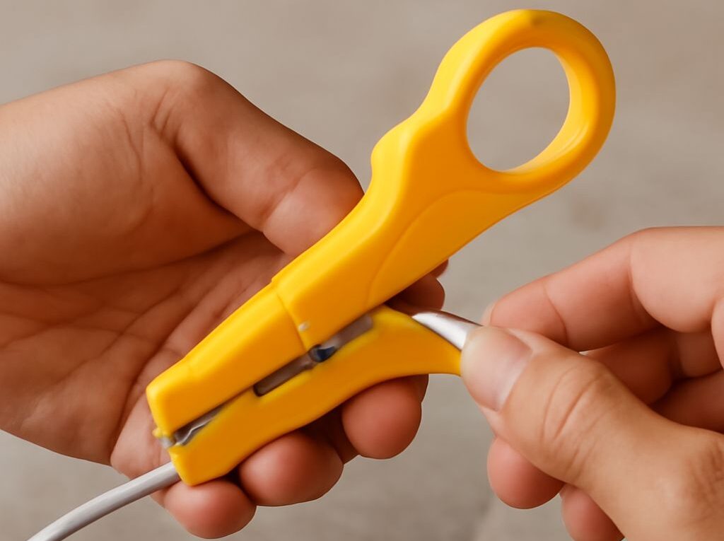
Coax Ethernet Adapter: Choose, Connect, and Test Your Setup
A coax ethernet adapter is an active network bridge: one powered unit converts Ethernet frames to a coax networking standard, and another unit converts them back to Ethernet. It is not the same as a passive coax plug or an Ethernet crimping tool. Examples include MoCA 2.5 equipment such as ScreenBeam ECB6250 and goCoax WF-803M, while products such as the Comtrend GCA-6000 use G.hn over coax. The systems use different protocols, so the adapters must support the same standard and compatible coax frequency range.
The correct setup depends on three separate decisions: which active coax system fits the cable path, which Ethernet port adapter or handoff fits the endpoint, and which termination tool matches the cable and modular plug. The workflow below keeps those functions separate and provides tests for both the cable and the completed network link.
Choose the Right Coax Ethernet Adapter System
Compare MoCA and G.hn by topology, frequency, and capacity
MoCA and G.hn are the main active technologies encountered in coax networking equipment. A typical installation has one adapter near a router or switch and a second adapter near a remote computer, access point, game console, or television. Some gateways include a built-in MoCA bridge, allowing one separate adapter to serve the remote endpoint.
- MoCA: MoCA adapters are designed for Ethernet networking over 75-ohm coax and commonly support point-to-point or point-to-multipoint layouts through a compatible splitter. MoCA 2.5 equipment can advertise up to 2.5 Gbps of aggregate physical-layer capacity, but the actual Ethernet handoff may be limited to 1 Gbps.
- G.hn: G.hn coax products use a different protocol and a vendor-defined profile. Their advertised capacity, supported topology, and coexistence features vary more substantially between models. G.hn adapters generally require matching G.hn equipment rather than a MoCA adapter on the other end.
- Frequency: The supported band determines whether the signal can pass through the existing splitters, amplifiers, wall plates, and filters. MoCA products commonly operate in the high-frequency coax range, often around 1125 to 1675 MHz, while exact G.hn and newer MoCA ranges vary by model. The adapter specification and every in-line component must cover the same band.
Choose a matched pair or a system explicitly designed for the intended network. A MoCA 2.5 adapter may communicate with some older MoCA equipment, but the connection normally operates at the older device’s capabilities. MoCA and G.hn should not be assumed to interoperate simply because both use coax.
Inspect the coax path before buying. A splitter rated only for television frequencies can attenuate or block the adapter signal. Replace unsuitable splitters with models rated for the system’s upper frequency, remove unnecessary splitters, and avoid legacy amplifiers that do not pass the selected band. If cable television or a cable modem shares the wiring, follow the adapter manufacturer’s instructions for entry filters, splitter placement, and service compatibility.
Check power requirements and the RJ45 handoff
Active coax adapters need local power, normally from an AC adapter. Check whether the product includes one, how many outlets are needed, and whether the adapter has a standby mode. A powered device at only one end cannot replace the second conversion point unless the other end is a built-in bridge in a gateway or networking device.
Next, check the Ethernet handoff. A coax adapter may provide one 10/100/1000BASE-T RJ45 port, a 2.5GbE port, or multiple ports. A 2.5 Gbps coax rating cannot deliver 2.5 Gbps to an endpoint if the adapter has only a gigabit RJ45 port. The router, switch, computer, and patch cable must also support the desired speed.
For example, a 2.5 Gbps MoCA link with gigabit Ethernet ports is suitable for a stable gigabit endpoint but cannot provide a 2.5GbE wired handoff. Conversely, a 2.5GbE port is useful only when the coax system and the connected network devices can negotiate above 1 Gbps.
Identify the Ethernet Port Adapter You Need
Choose RJ45, USB, or another active interface
An ethernet port adapter is selected according to the endpoint’s available port and operating system. The most direct arrangement is an RJ45 port on the coax adapter connected to the RJ45 port on a router, switch, access point, desktop, or network appliance with a standard twisted-pair cable.
- RJ45 to RJ45: Use this when the endpoint already has an Ethernet port. Match the port speed to the coax adapter and use a suitable Cat5e, Cat6, or higher-rated cable.
- USB-A or USB-C to Ethernet: Use this for a laptop, tablet dock, or computer without a built-in Ethernet port. The adapter contains active Ethernet electronics and may require an operating-system driver. USB 2.0 can limit a gigabit-class adapter, while USB 3.x or a compatible USB-C implementation is generally needed for higher speeds.
- Fiber or another media interface: A fiber media converter or specialized active adapter may be required when the endpoint uses an SFP, fiber, or industrial Ethernet connection. Confirm the electrical, optical, speed, and duplex requirements at both ends.
These devices are not interchangeable. A USB-to-Ethernet adapter adds an Ethernet interface to a host; it does not convert coax unless it specifically contains a coax transceiver. A passive RJ45-to-coax connector changes neither the signal format nor the network protocol. Likewise, a crimping tool only attaches a modular plug to a twisted-pair cable.
For a simple endpoint, the signal path should read: coax outlet or cable → active coax adapter → RJ45 Ethernet cable → endpoint port or USB Ethernet adapter. If a new cable is being made, terminate it before connecting expensive network equipment.
Select and Use an Ethernet Cable Crimping Tool
Match cable category, plug style, and crimp die
An ethernet cable crimping tool must match the modular plug and cable construction. Check these details before inserting the cable:
- Category: Use a plug rated for the cable category, such as Cat5e or Cat6. Cat6 cable can have a larger jacket or conductor diameter than a basic Cat5e plug accepts.
- Conductor type: Solid-conductor horizontal cable and stranded patch cable require compatible plugs. A plug designed for stranded conductors may not make a reliable connection on solid cable, and the reverse can also fail.
- Shielding: Shielded cable requires compatible shielded plugs and a tool that forms the shield connection. An unshielded plug does not preserve the cable’s shielding.
- Plug design: Standard plugs and pass-through plugs use different crimping actions. A pass-through tool cuts the conductors after they extend through the plug; a conventional plug requires the conductors to be cut to length before insertion.
- Die shape: The crimp die must press the plug’s contacts and strain relief in the correct locations. A tool that loosely fits the plug can produce uneven contact pressure or damage the housing.
A quality tool normally combines a jacket stripper, conductor cutter, and crimp die, but those functions do not guarantee compatibility with every plug. A separate flush cutter can produce a cleaner end on standard plugs. Avoid crushing the cable jacket or nicking the individual insulation during stripping.
Use the stripper/cutter and T568B order
For a straight-through patch cable, terminate both ends with the same wiring standard. T568B is common:
- White-orange
- Orange
- White-green
- Blue
- White-blue
- Green
- White-brown
- Brown
Arrange the conductors left to right with the plug contacts facing forward and the cable entering from behind. Keep the pair twists close to the plug; do not untwist more cable than necessary. For most structured-cabling terminations, limiting untwist to about 13 mm helps preserve pair performance. The jacket should extend inside the plug far enough for the strain-relief tab to grip it, rather than gripping only the thin insulated conductors.
Cut all eight conductors evenly, slide them fully into the plug, and verify that each conductor reaches the front while the jacket remains under the strain relief. Squeeze the tool completely once. For a standard plug, trim the conductors before insertion; for a pass-through plug, use the tool’s integrated cutter if it is designed for that plug.
T568A is also valid, but it should be used consistently or deliberately paired with T568B for a crossover cable. Modern Ethernet equipment usually supports auto-MDI/MDI-X, so a crossover is rarely necessary. The critical requirement is that each pair remains paired and the selected standard is correctly reproduced at the other end.
Connect and Test the Endpoint
Connect the coax adapters and Ethernet handoff
- Connect the first powered coax adapter to the router or switch with a tested Ethernet cable. If the router has built-in MoCA, connect the separate adapter to the remote coax location instead.
- Connect the second adapter to the remote coax outlet or cable run. Tighten F-connectors by hand; avoid excessive force that can damage the connector or wall plate.
- Power both active adapters and wait for their coax or network indicators to show an established connection. Pairing, encryption, or network-name settings may need to be configured according to the adapter instructions.
- Connect the remote RJ45 port to the endpoint. If the endpoint lacks Ethernet, connect the coax adapter to a compatible USB Ethernet adapter, dock, fiber converter, or other active Ethernet interface.
- Keep the initial test path simple. Temporarily remove extra switches, access points, and splitters so that a failure can be isolated to the coax link, the Ethernet cable, or the endpoint.
A direct coax connection between two compatible adapters is the easiest first test. If the adapters do not establish a link, check that both units use the same technology, that the coax path is continuous, and that every splitter passes the specified frequency. A television picture or cable-modem connection alone does not prove that the higher-frequency adapter signal can pass.
Verify the wire map, link negotiation, and throughput
Test a newly terminated Ethernet cable with a wire-map tester before relying on the network. Use the remote unit at the far end and look for all eight conductors in the correct sequence. The tester should identify opens, shorts, reversed conductors, crossed pairs, and split pairs. A cable can show continuity on all eight pins while still having a split pair, so a simple continuity light is less useful than a tester that reports pair assignment.
If shielding is present, use a tester that can check shield continuity when that connection matters. Correct the plug if the result shows a missing conductor, an incorrect T568 order, a conductor that did not reach the contacts, or a jacket that was not captured by the strain relief.
After the cable passes, inspect the negotiated Ethernet speed in the computer, switch, router, or USB adapter status page. A gigabit link should negotiate at 1000 Mbps, while a compatible 2.5GbE path should show 2.5 Gbps. A result of 100 Mbps often indicates a damaged pair, an incorrectly crimped plug, an unsuitable patch cable, or a port limited to Fast Ethernet. Leave speed and duplex on auto-negotiation unless a specific managed-network design requires manual settings.
Finally, measure throughput across the coax path rather than relying only on an internet speed test. A wired iperf3 test between two local endpoints helps separate the adapter system from the broadband connection. Test one direction and then the other, and repeat with both endpoints connected by Ethernet rather than Wi-Fi. Compare the result with the negotiated port speed and the adapter’s stated physical-layer capacity. Lower application throughput is normal because of protocol overhead, coax signal conditions, splitter loss, and traffic from other nodes; a 2.5 Gbps PHY rating does not guarantee 2.5 Gbps of usable file-transfer speed.