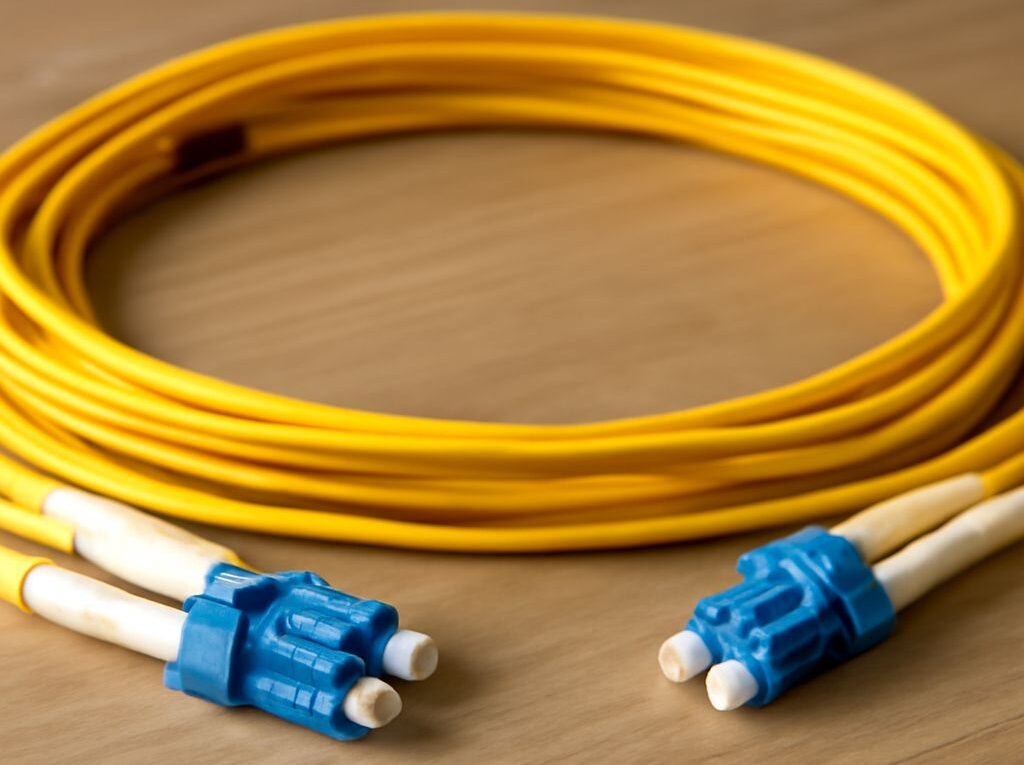
Fiber optic network cable vs. copper: speeds, distance, and wire colors
A fiber optic network cable is usually the better choice for long runs, high aggregate bandwidth, electrically noisy areas, and links between buildings. Twisted-pair copper is generally more practical for horizontal office cabling, short equipment connections, and Power over Ethernet (PoE). The correct choice depends on the Ethernet standard, cable category or fiber grade, required reach, interface, and test results—not speed claims alone.
Fiber does not use an RJ45 conductor sequence. T568A and T568B apply to copper twisted-pair cables terminated with 8P8C modular plugs or jacks. Fiber uses optical strands, fiber positions, polarity rules, and transceivers instead.
Fiber optic network cable: multimode and single-mode applications and reach
Fiber Ethernet sends data as light through glass rather than electrical signals through copper. It provides high bandwidth, low attenuation, and strong resistance to electromagnetic interference (EMI), radio-frequency interference, and ground-potential differences. Those properties make it useful for backbone links, data centers, industrial environments, security systems, and connections between buildings.
Fiber selection starts with the mode or grade:
- Multimode fiber: OM1 uses a 62.5-micron core, while OM2, OM3, OM4, and OM5 typically use a 50-micron core. Multimode is suited to building backbones and data-center links where distances are usually several hundred meters or less.
- Single-mode fiber: OS1 and OS2 use a much smaller core and support substantially longer distances. OS2 is commonly selected for campus, metropolitan, carrier, and inter-building networks.
Reach is determined by the fiber grade, Ethernet standard, optical wavelength, transceiver, connector losses, and the number of splices and patch points. Representative distances include:
- OM3: 10GbE over up to about 300 meters with the appropriate multimode optics.
- OM4: 10GbE over up to about 400 meters; some higher-speed standards reach roughly 100 to 150 meters depending on the transceiver.
- OM5: Designed for short-wavelength-division multiplexing applications and commonly supports similar short-reach data-center distances, depending on the standard and optics.
- OS2: 10GbE long-reach optics commonly support up to 10 kilometers, while longer-reach systems can extend much farther with compatible carrier or data-center equipment.
Fiber Ethernet standards include 1000BASE-SX, 10GBASE-SR, 10GBASE-LR, and numerous 25, 40, 100, and 400GbE variants. The standard identifies the signaling method and expected media, but the transceiver still determines whether a particular link uses multimode or single-mode fiber, which wavelength it uses, and how far it can run.
Fiber bandwidth is not expressed in exactly the same way as copper cable bandwidth. Multimode specifications often list modal bandwidth in MHz-km, while Ethernet equipment is rated in gigabits per second. A cable with a higher modal-bandwidth rating can support a longer or faster optical link, but only when the connected optics and Ethernet standard support that rate.
Fiber has limitations as well. It cannot normally deliver power to a remote endpoint, requires compatible optical modules or media converters, and is more sensitive to contamination, excessive bend radius, and poor end-face condition. A fiber jacket color can provide a useful identification clue—yellow is commonly associated with single-mode, orange with older multimode grades, aqua with OM3 or OM4, and lime green with OM5—but jacket colors are conventions, not a substitute for the cable marking or test record.
Ethernet cable speeds: copper categories, standards, and reach
Copper twisted-pair cabling is common for workstations, access points, phones, cameras, printers, and switches. It can carry both data and PoE, uses familiar RJ45-style interfaces, and is economical for runs within the standard structured-cabling limit. The usual maximum permanent-link channel is 90 meters, with patch cords bringing the total channel to approximately 100 meters.
The cable category sets electrical performance, but the connected Ethernet standard sets the actual data rate. Representative copper capabilities are:
- Cat5e: Supports 1000BASE-T at 1Gbps over up to 100 meters. Many network devices also use 2.5GBASE-T over a full 100-meter channel when the installation meets the relevant performance requirements.
- Cat6: Supports 1GbE and commonly supports 2.5GBASE-T and 5GBASE-T to 100 meters. 10GBASE-T is generally limited to about 55 meters, depending on alien crosstalk and installation conditions.
- Cat6A: Supports 10GBASE-T to 100 meters and provides stronger control of crosstalk than Cat6. It is a common choice for new 10GbE horizontal cabling.
- Cat8: Designed for 25GBASE-T and 40GBASE-T applications over up to about 30 meters, including patching. It is primarily used for short data-center connections rather than ordinary office drops.
These are representative limits, not guarantees for every installed link. Connector quality, untwisting at termination, bend radius, bundle size, patch-panel performance, temperature, and nearby cables can reduce the usable margin. A higher category cable also does not force a switch to operate at a higher rate; both endpoints must support the Ethernet standard.
Copper Ethernet standards commonly encountered in access networks include 100BASE-TX, 1000BASE-T, 2.5GBASE-T, 5GBASE-T, and 10GBASE-T. Their speeds are sometimes described as Ethernet cable speeds, but the phrase can obscure an important distinction: the cable is a passive transmission medium, while the network interface negotiates or is configured for the operating rate.
Copper has a practical advantage when PoE is required. The same four-pair cable can deliver data and electrical power to compatible wireless access points, cameras, phones, and other devices. Copper is also easier to terminate and test in many field installations.
Its main disadvantages are distance and interference. Copper signaling attenuates over length and can suffer from near-end crosstalk, far-end crosstalk, alien crosstalk, and EMI. Shielded cable, proper bonding, separation from power wiring, and compliant installation practices can reduce these effects, but they do not turn copper into a long-distance medium. Fiber is normally preferred where electrical isolation or a run beyond the copper channel limit is required.
Choose interfaces: connectors, transceivers, compatibility, and testing
Interface matching should happen before selecting a cable. A copper switch port with an integrated 10GBASE-T PHY requires a compatible twisted-pair channel and RJ45-style termination. A switch port that accepts an SFP, SFP+, SFP28, or QSFP module requires an optical or direct-attach solution matched to that slot and its supported standards.
Common copper interfaces use 8P8C modular connectors, although “RJ45” is the term used in most network installations. Fiber commonly uses duplex LC connectors for switch links, while SC connectors remain common in some legacy and building systems. MPO or MTP multifiber connectors support parallel-fiber applications such as certain 40GbE and 100GbE links. Connector shape alone does not establish compatibility.
A fiber transceiver must match the following characteristics:
- Ethernet rate and standard, such as 10GBASE-SR or 10GBASE-LR
- Multimode or single-mode fiber type
- Optical wavelength and transmission design
- Required reach and link budget
- Connector type and fiber polarity
- Switch, router, or media-converter slot type
For example, a short-reach SR optic is intended for multimode fiber, while an LR optic is commonly intended for single-mode fiber. Inserting a physically compatible module does not guarantee that the switch will recognize it, that the wavelength will match, or that the link budget will support the installed distance. Vendor coding and equipment compatibility may also matter.
Fiber-to-copper media converters can join different media, but they do not remove the limits of either side. The copper segment still needs a compliant category and channel length, and the optical modules on each end still need matching mode, wavelength, speed, and reach characteristics.
Testing verifies the installed link rather than relying on the cable label. Copper certification tests typically include wiremap, length, insertion loss, return loss, and crosstalk measurements such as NEXT and ACR-F. A basic continuity test can identify an open, short, or crossed pair, but it cannot certify that a Cat6A channel supports 10GBASE-T.
Fiber testing begins with inspection and cleaning of every end face. Depending on the installation requirement, technicians use a light source and power meter or an optical-loss test set to measure insertion loss. An OTDR can help locate high-loss events, bad splices, and reflections along the cable. Polarity, connector cleanliness, bend damage, and the measured loss budget should be checked before troubleshooting active equipment.
ethernet wire colors: T568A and T568B pin order, not fiber order
T568A and T568B are copper termination conventions. They specify which colored twisted pair is placed on each pin of an 8P8C plug or jack. The two standards use the same four pairs but exchange the green and orange pairs.
T568A pin order, from pin 1 through pin 8:
- White/green
- Green
- White/orange
- Blue
- White/blue
- Orange
- White/brown
- Brown
T568B pin order, from pin 1 through pin 8:
- White/orange
- Orange
- White/green
- Blue
- White/blue
- Green
- White/brown
- Brown
A straight-through copper patch cable uses the same standard at both ends: T568A-to-T568A or T568B-to-T568B. A cable terminated T568A at one end and T568B at the other is a crossover cable. Most modern Ethernet equipment supports auto-MDI/MDI-X, so a crossover is rarely needed for ordinary endpoint connections, but consistent termination remains important for structured cabling.
The ethernet wire colors above apply only to copper pair conductors. Fiber cable has no T568A or T568B conductor order because it does not contain four copper Ethernet pairs. Fiber identification may use jacket colors, colored buffer tubes, numbered strands, connector keying, or a documented polarity method. Those markings identify the fiber or its position; they do not create an RJ45 pinout.
For that reason, a fiber link should be documented by its fiber type, strand or tube number, connector and polarity arrangement, transceiver model or optical standard, and test results—not by assigning T568 colors to the optical strands.