RJ45 Plug Wiring for a 100-Foot Cat6 Run Through a Coax Adapter
Reliable rj45 plug wiring for a 100-foot Cat6 run uses solid-copper cable, one consistent pinout at both ends, and a wire-map test before the cable is connected to an active coax network adapter. A 100-foot copper segment is approximately 30.5 meters, well below the usual 100-meter Ethernet channel limit, provided patch cords, jacks, couplers, and other copper sections are included in the calculation.
The complete path should be validated in stages: test the first copper segment, test the second copper segment, verify the coax adapter link, and then measure end-to-end performance. The coax adapters are active Ethernet-to-coax bridges, not passive couplers, so their model limits, coax topology, frequency range, power, and endpoint capacity also determine the result.
Plan the 100-foot Cat6 run: cable category, conductor type, pathway, and channel length
For each copper segment, use a solid-copper Cat6 cable with a conductor size appropriate to the RJ45 plugs, usually 23 or 24 AWG. Cat6 supports Gigabit Ethernet over a properly installed 100-meter channel and may support higher rates over shorter distances when the equipment and installation meet the required specifications. The cable category should match the intended speed; do not assume that a cable marked “Cat6” will perform correctly if its construction or termination is poor.
- Choose solid copper: Avoid copper-clad aluminum (CCA) cable for permanent Ethernet wiring. CCA has higher resistance and may not meet the electrical requirements of the Ethernet category printed on the jacket.
- Match the plug: Use RJ45 plugs designed for Cat6 and the cable’s conductor size. Solid-conductor plugs and stranded patch-cable plugs are not always interchangeable.
- Plan the pathway: Keep the cable away from power wiring, fluorescent-ballast wiring, motors, and other strong sources of electrical interference. Use suitable conduit, raceway, or cable supports, and observe local requirements for plenum, riser, outdoor, or direct-burial cable.
- Protect the bend radius: Do not sharply kink, crush, staple, or tightly bundle the cable. Follow the cable manufacturer’s minimum bend radius, especially near plugs and wall penetrations.
Count the entire copper channel, not only the cable pulled through the pathway. The calculation includes the 100-foot cable, patch leads, wall jacks, keystone modules, couplers, and any short cable between the Ethernet device and the coax adapter. The common structured-cabling limit is 90 meters for permanent horizontal cable plus up to 10 meters of patch cords, for a 100-meter channel. A 100-foot section normally leaves substantial margin, but two separate 100-foot copper sections should not be treated as one continuous Ethernet channel through the coax system.
A typical layout is router or switch to Cat6 cable to the first adapter, coax between the adapter locations, and the second adapter to Cat6 cable to the remote switch, computer, access point, or other endpoint. Each copper side has its own Ethernet link and must satisfy its own length and termination requirements.
RJ45 plug wiring: T568A/T568B order, crimping, and wire-map tests
Use either T568A or T568B, but use the same standard at both ends of a straight-through cable. T568B is common in many installations. Viewed with the plug contacts facing away and the locking tab underneath, the conductor order from pin 1 through pin 8 is:
- White-orange
- Orange
- White-green
- Blue
- White-blue
- Green
- White-brown
- Brown
T568A changes only the orange and green pairs:
- White-green
- Green
- White-orange
- Blue
- White-blue
- Orange
- White-brown
- Brown
Do not mix A on one end and B on the other unless a crossover cable is specifically required. Most modern Ethernet equipment supports automatic crossover, but a straight-through cable with the same standard at both ends is the predictable choice.
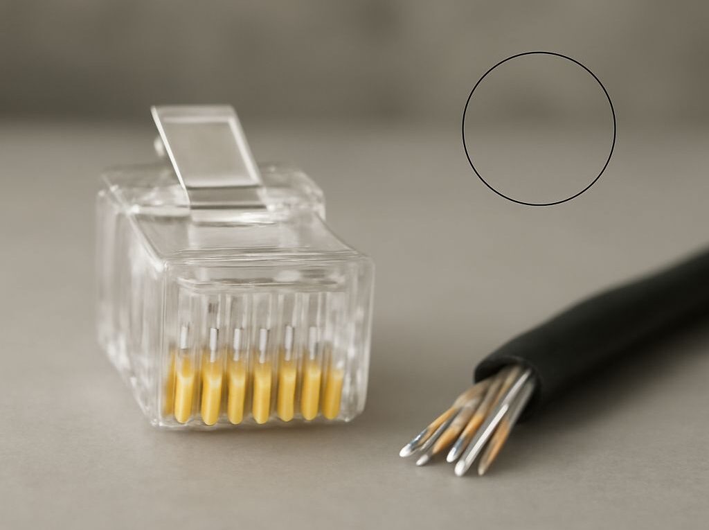
To terminate a plug, cut the cable square, slide on the boot if one is used, and remove only enough jacket to arrange the conductors. Separate the four pairs, place them in the selected order, and keep the pair twists as close to the plug as possible. Excessive untwisting can increase crosstalk and reduce performance. Trim the conductors evenly, insert them fully into the plug, and check that the jacket extends inside the plug so the strain relief grips the jacket rather than the individual wires.
Crimp the plug with a tool designed for that plug and conductor type. The contacts should pierce the conductors evenly, the latch should be intact, and the cable should not pull out when lightly tugged. If the plug has a load bar or pass-through design, follow its specific assembly instructions instead of forcing the conductors into a different arrangement.
Test every newly terminated cable with a wire-map tester before connecting network equipment. The result should show pins 1 through 8 in the same order at both ends. A proper test can identify opens, shorts, reversed conductors, crossed pairs, and split pairs. A continuity-only test may miss a split pair, so a tester that reports pair integrity is preferable. For a critical or high-speed installation, certification testing provides more information than a basic LED tester, including insertion loss, return loss, and crosstalk.
Connect the active coax network adapter pair: topology, splitters, frequency, power, and endpoints
Connect the first adapter’s Ethernet port to the router or switch with a tested Cat6 cable. Connect its coax port to the coax outlet or cable run. At the remote location, connect the second adapter to the coax system and connect its Ethernet port to the remote device or switch with the second tested copper segment. Each adapter requires the power supply specified by its manufacturer, and both units should show power and coax-link status before troubleshooting Ethernet addressing.
Use adapters designed to work as a pair or within the same supported adapter family. A passive coax coupler cannot perform this conversion. The adapters actively modulate Ethernet traffic onto coax and recover it at the other end, so their supported coax standard, maximum coax distance, signaling rate, and network mode matter.
- Topology: A direct point-to-point coax run is the simplest arrangement. A shared coax distribution network can support more than two adapters when the adapter system supports that mode and endpoint count.
- Splitters: Every splitter in the path must cover the adapter’s operating frequency and have suitable insertion loss. Use the fewest splitters possible, terminate unused ports where appropriate, and do not assume a television splitter will support the adapter’s full band.
- Frequency coexistence: If the coax also carries cable television, broadband service, or another RF system, confirm that the adapter frequency range can coexist with those services. A compatible MoCA filter, amplifier, or point-of-entry arrangement may be required. An incompatible amplifier or filter can block the adapter signal.
- Power: Both adapters need stable power, and some models require a particular power injector or approved supply. Power LEDs alone do not prove that the coax path is usable; the coax or network link LED must also establish.
- Endpoint count: A two-unit kit generally provides one local and one remote bridge. Additional rooms require a supported multi-endpoint design, adequate coax signal levels, and enough Ethernet switch ports.
Do not count only the coax length when checking end-to-end limits. The copper segments, coax path, splitter loss, adapter processing, and Ethernet ports form a combined connection with several independent limits. The adapter manufacturer’s coax distance and topology specifications control the coax portion, while the Ethernet channel limit controls each copper portion.
Test each segment and the complete path: link state, addressing, and throughput
Test in this order so a failure is isolated rather than hidden inside the complete installation.
- Test the first copper segment. Use the wire-map tester, then connect it between a switch and the local adapter. Confirm that the Ethernet link negotiates at the expected speed and duplex. A link that falls to 100 Mbps may indicate a damaged conductor, bad termination, poor plug compatibility, or an equipment limitation.
- Test the second copper segment. Repeat the wire-map and link-speed checks between the remote adapter and the remote endpoint or switch. Test this cable independently if possible, rather than assuming both terminations are correct because one side works.
- Establish the coax link. Power both adapters, connect the coax path, and check the power, coax, and Ethernet indicators. If the coax link does not establish, remove splitters temporarily and test the adapters over the shortest approved direct coax connection. Restore the distribution components one at a time.
- Check addressing. In bridge mode, the adapters normally pass Ethernet frames without requiring separate IP addresses. The remote endpoint should receive an address from the same DHCP router and appear on the same local subnet as devices connected directly to that router. If an adapter has router mode, disable it or configure it deliberately to avoid double NAT.
- Measure throughput. First test between two wired endpoints on the same switch to establish a local baseline. Then run a wired throughput test across the complete route, such as an iperf3 TCP test with a server on one side and a client on the other. Avoid Wi-Fi during this measurement.
Record negotiated Ethernet speed, coax link state, packet errors, and measured throughput. The practical end-to-end result is limited by the slowest component: the local Ethernet port, first copper segment, coax adapter pair and coax path, remote copper segment, remote switch or endpoint port, or the tested protocol. A high adapter link rate is a physical-layer figure, not a guarantee of application throughput. If the full-path result is unexpectedly low, retest each copper cable, bypass splitters, inspect adapter link rates, and compare the result with a direct wired baseline.